Motor structure

a motor and structure technology, applied in the direction of dynamo-electric machines, electrical apparatus, magnetic circuit shape/form/construction, etc., can solve the problems of unavoidable defects in the method, difficult and relatively low torque, so as to increase the rotating speed efficiently, stable rotation, and increase the torque

Inactive Publication Date: 2008-06-05
INVENTEC CORP
View PDF18 Cites 13 Cited by
  • Summary
  • Abstract
  • Description
  • Claims
  • Application Information

AI Technical Summary

Benefits of technology

[0008]In view of the above, in order to solve the above problems and to use the rotor and stator structure of the motor itself to achieve the effect that the rotor is stably rotated so as to increase the rotating speed efficiently and to increase the torque when the motor is operated under the pole, the present invention provides a motor structure, wherein a stator is respectively disposed at the internal side and external side of the rotor. Thus, the pole pushing force or the pole pulling force for the rotor are generated simultaneously to increase the rotating speed of the rotor. Moreover, a double stator structure provides a larger magnetic force to directly increase the torque of the motor. Besides, a balancing effect is achieved under both the pushing forces applied to the rotor by the internal and external stators, which enables the rotor to rotate stably without any offsets.
[0014]The present invention not only solves the defects of the prior art, but also has advantages that are difficult to be achieved in the prior art. (1) The middle rotor is rotated under both an external pushing force and an external attractive force that are generated by the internal stator and the external stator simultaneously due to the effect that the like poles are repulsive to each other or unlike poles are attractive to each other. The external force is obviously stronger than that generated by using a single stator corresponding to the rotor in the prior art. Thus, the middle rotor in the present invention comes into a high speed rotating state during a short time period and the rotating speed is relatively high. Meanwhile, the shaft diameter of the middle rotor is not limited, so that a stronger torque may be generated. (2) By using a double-stator structure having the internal and external stators, a pushing force and an attractive force that may counteract with each other are simultaneously generated corresponding to the internal and external sides of the middle rotor. Therefore, a stabilized effect is achieved while the middle rotor is rotated.

Problems solved by technology

However, the method has following unavoidable defects.
However, in this way, the external rotor is disturbed by other external forces, and as a result, the rotating speed is difficult to be increased, and the torque is relatively low.
However, the shaft diameter of the internal rotor is too small to be applied to various operation fields, thus, the operating fields are always limited, and it's difficult to increase the torque efficiently with a limited shaft diameter, which causes an invisible waster of energy.

Method used


Image

  • Motor structure
  • Motor structure
  • Motor structure

Examples


Embodiment Construction

[0026]To further understand the objective, configuration characteristics, and function of the present invention, the present invention is illustrated below in detail with reference to relevant embodiments and drawings.

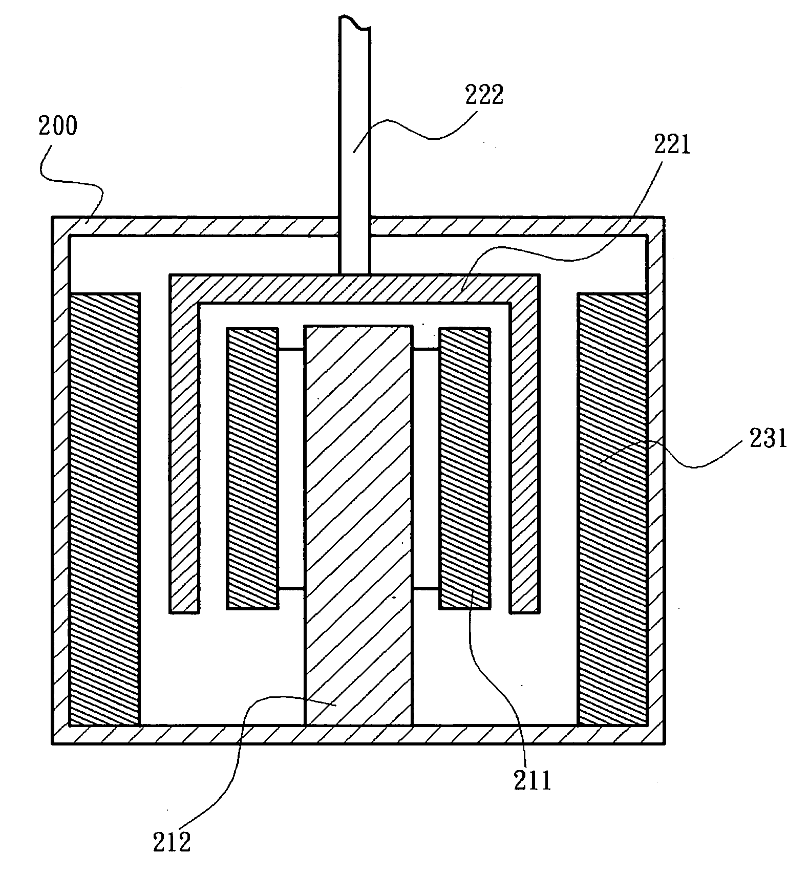
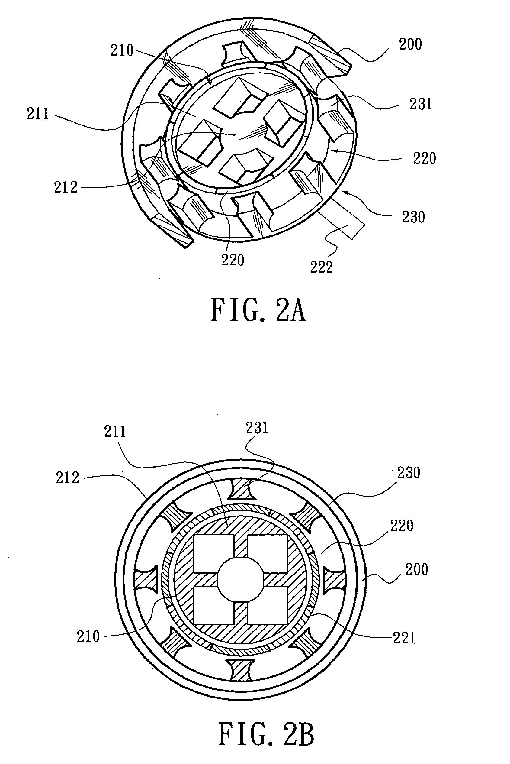
[0027]As shown in FIGS. 2A, 2B, and 2C, they are a 3-dimentional cutaway view, a side view, and a cross-sectional top view of a motor structure of the present invention. The motor structure mainly includes a housing 200, a middle rotor 220, an internal stator 210, and an external stator 230.

[0028]The middle rotor 220 has a revolving shaft 222 and an annular magnetic section 221. The revolving shaft 222 is pivotally mounted on the housing 200. The annular magnetic section 221 is an inverted U-shaped cover body in this embodiment, which is coaxially fitted to the revolving shaft 222. The annular magnetic section 221 has a plurality of circularly disposed magnetic segments and poles of the adjacent magnetic segments are unlike. In this embodiment, the annular magnetic sec...


PUM


Abstract

A motor structure including a revolving shaft, internal stators, middle rotors, and external stators is provided. The revolving shaft is an axle center, and the internal stators, middle rotors, and external stators are arranged in an outward radial direction. The middle rotors are circularly disposed with magnetic segments, and the poles of adjacent magnetic segments are unlike. Besides, the internal stators are circularly disposed with magnetic generating sections having the like pole and alternatively corresponding to the magnetic segments. The external stators are disposed with magnetic corresponding sections corresponding to the magnetic segments one by one. Moreover, the pole of the magnetic corresponding sections that correspond to the magnetic generating sections is the same as that of the magnetic generating sections. On the other aspect, the pole of the magnetic corresponding sections that do not correspond to the magnetic generating sections is different from that of the magnetic generating sections.

Description

BACKGROUND OF THE INVENTION[0001]1. Field of Invention[0002]The present invention relates to a motor structure, and more particularly, to a motor structure disposed with a double-stator structure to enhance the magnetic force for driving a rotor.[0003]2. Related Art[0004]As shown in FIGS. 1A and 1B, they are schematic views of a nowadays conventional motor rotating structure. Generally, the motor is classified into two categories of motor structures: one is the first type of motor with an internal stator and an external rotor; and the other is the second type of motor with an internal rotor and an external stator.[0005]A main core of the first type of motor rotating structure consists of an internal stator 110 and an external rotor 120 that are arranged correspondingly. Generally, the external rotor 120 is formed by a permanent magnet or by a metal that undergoes the magnetization process. The external rotor 120 has a plurality of external magnetization segments 121 thereon. Besides...

Claims


Application Information

Patent Timeline
Patent Type & Authority Applications(United States)
IPC IPC(8): H02K16/04
CPCH02K16/04
Inventor CHEN, WIN-HAWCHANG, CHEN-YUEH
Owner INVENTEC CORP
Why Eureka
Try Eureka