Inductively-Powered Power Transfer System With One Or More Independently Controllable Loads

a power transfer system and independent control technology, applied in the direction of transformers/inductance circuits, electrical devices, inductances, etc., can solve the problems of unfavorable, environmentally inert road studs powered in this way, and unaffected by roading

Active Publication Date: 2008-06-05
AUCKLAND UNISERVICES LTD
View PDF3 Cites 23 Cited by
  • Summary
  • Abstract
  • Description
  • Claims
  • Application Information

AI Technical Summary

Benefits of technology

[0005]It is an object of the present invention to provide an IPT system with independently controllable loads or operating units. One specific object is to provide an IPT road-stud system in which the operational characteristics of individual road-studs, or groups of studs, is independently controllable. Other objects of the invention include the provision of an IPT system or a narrow band modulated data transmission system which reduces or overcomes one or more of the abovementioned limitations, or which at least provides the public with a useful alternative.STATEMENTS OF THE INVENTION

Problems solved by technology

Such an advantage is not possible with a moving IPT monorail system.
Road-studs powered in this way are environmentally inert and unaffected by roading or weather conditions.

Method used


Image

  • Inductively-Powered Power Transfer System With One Or More Independently Controllable Loads
  • Inductively-Powered Power Transfer System With One Or More Independently Controllable Loads

Examples


example one

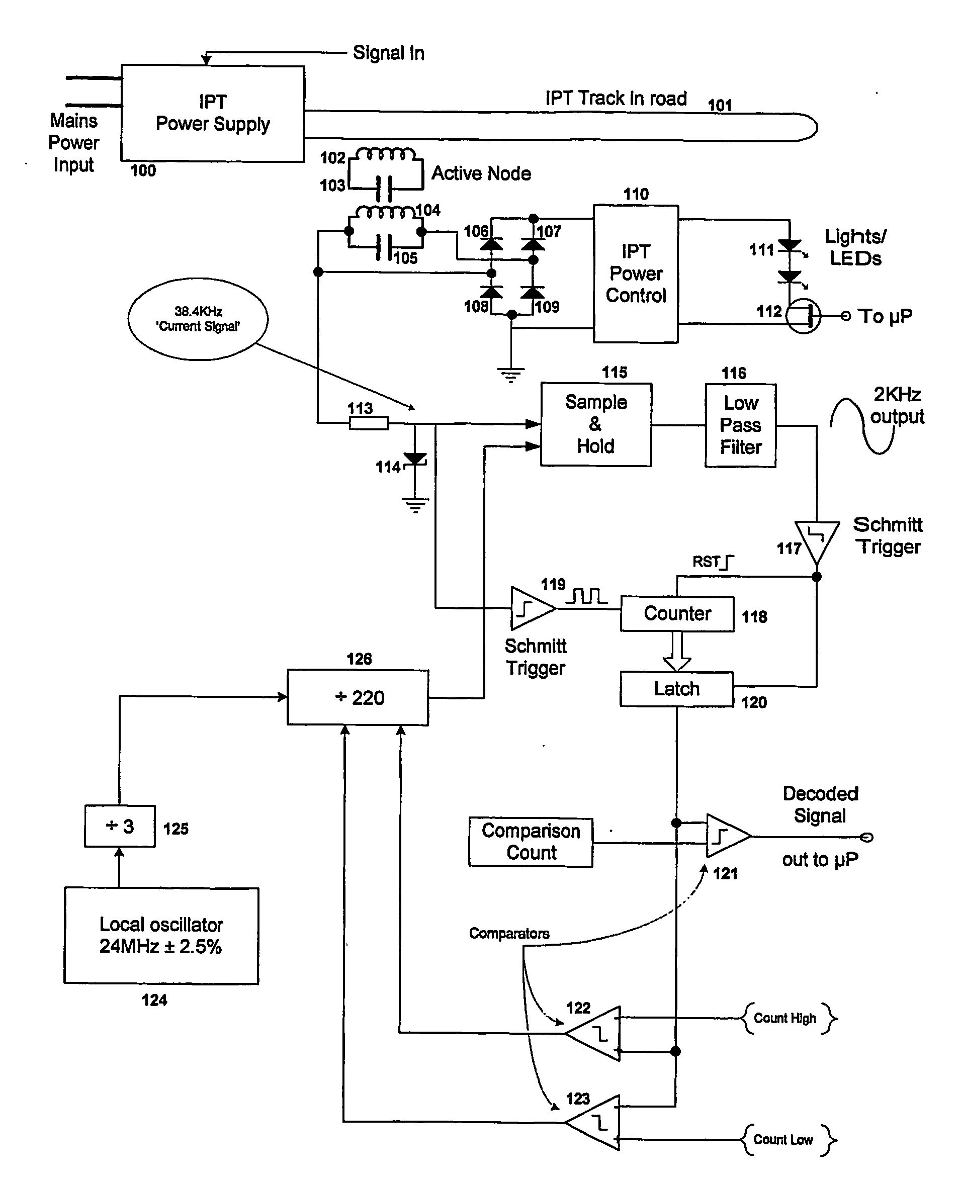
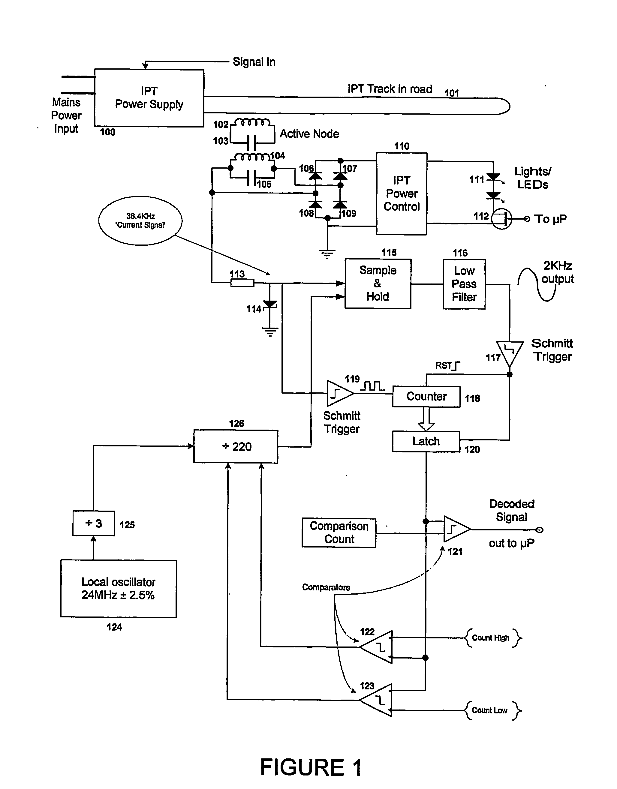
[0077]In the road-stud the digital system operates at a nominal 38.4 kHz but generates a ‘more or less’ stable frequency say 6% lower than this nominal frequency, 36.096 kHz. The incoming frequency of 38.4 kHz from the primary conductor track circuit, with FM, is filtered to remove some noise and make it more stable. This signal is representative of the frequency of the current in the primary conductor and is then sampled with a sample and hold circuit at this 36.096 kHz frequency to produce a sampled sine wave output signal at 2.304 kHz, which can then be put through a low pass filter to remove unwanted noise. With the FM present, 38.985 kHz is converted to 2.889 kHz and 37.833 kHz is converted to 1.737 kHz. Thus the frequency of the current in the primary conductor has been effectively aliased down. These frequencies are easily and unambiguously detected counting at quite modest frequencies, for example 1 MHz. Measuring the periods to 1 microsecond gives an expected value (no modu...

example two

[0081]As mentioned above, an accurate reference frequency is not available on the road-stud so narrow-band variations in the primary conductive track circuit frequency cannot be detected by simply measuring their period as there is insufficient resolution to get sensible results with limited accuracy frequency references. To improve the resolution the frequency changes can be increased in relative terms by mixing the observed track frequency down. For example if the track signal at a frequency of 38.4 kHz is multiplied by a signal of 36.4 kHz there will be two output frequencies at 2 kHz—the difference frequency, and 74.8 kHz—the sum frequency. When the track frequency changes by 1.5% (600 Hz), these frequencies change to 2.6 kHz and 75.4 kHz. If the high frequency ‘sum’ signal is eliminated the low frequency ‘difference’ signal now carries all of the information. As all of the interference in the road-stud is at 38.4 kHz the 2 kHz signal may be compared with it. This is a simple pr...

example three

[0096]In another innovation the circuit of FIG. 1 may be used without change to produce a self-calibrating system where exact tuning of the divider for the local oscillator 124 is obtained whether or not any data is actually being sent. Here power supply 100 switches the frequency of operation on a continuous basis by for example + / −0.8%. Thus the IPT track 101 has a frequency in it of typically 38.1 kHz or 38.7 kHz and switches between the two at a rate of perhaps 400 Hz for example. The circuit of FIG. 1 will now try to control the average frequency to be 38.4 kHz by adjusting the division ratio for divider 126. Here comparators 121, 122, and 123 can all use the same count as the comparison value. In fact two of these can be simply ignored and one comparator can be used set to the average expected count. If the count is high this is the decoded signal for a ‘1’ and it is a signal to increase the division ratio; if it is low then the data is a zero, and a signal to reduce the divis...


PUM

PropertyMeasurementUnit
currentaaaaaaaaaa
currentaaaaaaaaaa
power frequencyaaaaaaaaaa

Abstract

The present invention provides a system for controlling one or more operating unites in an inductive power transfer (IPT) system. Each operating unit includes a pick-up coil that takes power from a primary conductor or track over an air gap. The operating unit is controlled by frequency modulating the primary conductor power supply to send a control instruction which is decoded by the operating unit. The instruction is decoded by generating a signal using a local oscillator in the operating unit and using the signal to detect changes in the frequency of the current in the primary conductor. Such a system can be used, for example, to control inductively powered road-studs that include a light source for controlling traffic on a roadway. A narrow band modulated data transmission system and method for controlling an operating unit are also provided.

Description

FIELD OF THE INVENTION[0001]This invention relates to apparatus and methods enabling the independent control of operational characteristics of one or more loads or operating units associated with an inductive power transfer (IPT) system.BACKGROUND TO THE INVENTION[0002]One application of an IPT system where individual control of the loads is desirable is inductively powered road-studs. These are now a recognized traffic control technique, and are described in U.S. Pat. No. 6,459,218. As described in U.S. Pat. No. 6,459,218, a very low frequency (VLF) current is passed through a conducting wire (which may be referred to as a primary conductor or track) buried under the roadway. Road-studs sensitive to the magnetic field created by that wire are placed on the surface of the roadway and take power from the buried conductor by mutually coupling some of the magnetic field through a pick-up coil in the road-stud. The pick-up coil may be tuned with a capacitor to augment the power transfer...

Claims


Application Information

Patent Timeline
Patent Type & Authority Applications(United States)
IPC IPC(8): H05B41/36H01F27/42H05B41/00
CPCH03D3/04H02J5/005H02J50/10H02J50/12
Inventor BOYS, JOHN TALBOT
Owner AUCKLAND UNISERVICES LTD
Why Eureka
Try Eureka