
Motor control method and motor control apparatus

a control method and motor technology, applied in the direction of motor/generator/converter stopper, process and machine control, etc., can solve the problems of excessive temperature rise of motor windings, damage to motors, and difficulty in performing desired demagnetization, so as to increase the armature magnetic flux and efficiently demagnetize permanent magnet pieces

Inactive Publication Date: 2008-06-05
HONDA MOTOR CO LTD
View PDF3 Cites 29 Cited by
  • Summary
  • Abstract
  • Description
  • Claims
  • Application Information

AI Technical Summary

Benefits of technology

[0012]According to the motor control method described above, it is possible to prevent excessively large torque fluctuations from occurring by short circuiting a plurality of phases of the motor in the state of the rotational frequency of the motor that is rotationally driven by the driving source being equal to or greater than a predetermined rotational frequency, the short-circuit torque that occurs when having short-circuited the plurality of phases of the motor being less than a predetermined value, and the fluctuations in the phase currents corresponding to the rotational frequency when having short circuited the plurality of phases of the motor (that is, short circuit currents) being less than the predetermined fluctuations. Moreover, it is possible to stably impress the armature magnetic flux of the desired weak magnetic field phase onto the permanent magnet pieces of the rotor, possible to cause the permanent magnet pieces to undergo self heating due to overcurrent loss caused by this armature magnetic flux, and possible to suitably and efficiently demagnetize the permanent magnet pieces.
[0014]In this case, for example when the detected value of a short circuit current falls to the predetermined value or less, or when the induced voltage constant that can be calculated from the detected value of the short circuit current falls to the predetermined value or less, it is determined that the desired demagnetization is complete. Then, by stopping the short circuiting of the plurality of phases of the motor and the rotational driving of the motor by the driving source, it is possible to prevent excessive energy consumption. Also, it is possible to prevent heat damage from occurring in the motor by stopping the short circuiting of the plurality of phases of the motor and the rotational driving of the motor by the driving source in the case of, for example, the temperature of the permanent magnet pieces and the temperature of the stator increasing to the predetermined value or higher.
[0016]According to the motor control apparatus of the above-described constitution, it is possible to prevent excessively large torque fluctuations from occurring by short circuiting a plurality of phases of the motor in the state of the rotational frequency of the motor that is rotationally driven by the driving source being equal to or greater than a predetermined rotational frequency, the short-circuit torque that occurs when having short-circuited the plurality of phases of the motor being less than a predetermined value, and the fluctuations in the phase currents corresponding to the rotational frequency when having short circuited the plurality of phases of the motor (that is, short circuit currents) being less than predetermined fluctuations. Moreover, it is possible to stably impress the armature magnetic flux of the desired weak magnetic field phase onto the permanent magnet pieces of the rotor, possible to cause the permanent magnet pieces to undergo self heating due to overcurrent loss caused by this armature magnetic flux, and possible to suitably and efficiently demagnetize the permanent magnet pieces.
[0018]In this case, it is possible to suitably and rotationally drive the motor with the internal combustion engine without the need to provide a special apparatus as the driving source and possible to suitably and efficiently demagnetize the permanent magnet pieces.
[0020]In this case, for example when the detected value of a short circuit current falls to the predetermined value or less, or when the induced voltage constant that can be calculated from the detected value of the short circuit current falls to the predetermined value or less, it is determined that the desired demagnetization is complete. Then, by stopping the short circuiting of the plurality of phases of the motor and the rotational driving of the motor by the driving source, it is possible to prevent excessive energy consumption. Also, it is possible to prevent heat damage from occurring in the motor by stopping the short circuiting of the plurality of phases of the motor and the rotational driving of the motor by the driving source in the case of, for example, the temperature of the permanent magnet pieces and the temperature of the stator increasing to a predetermined value or higher.
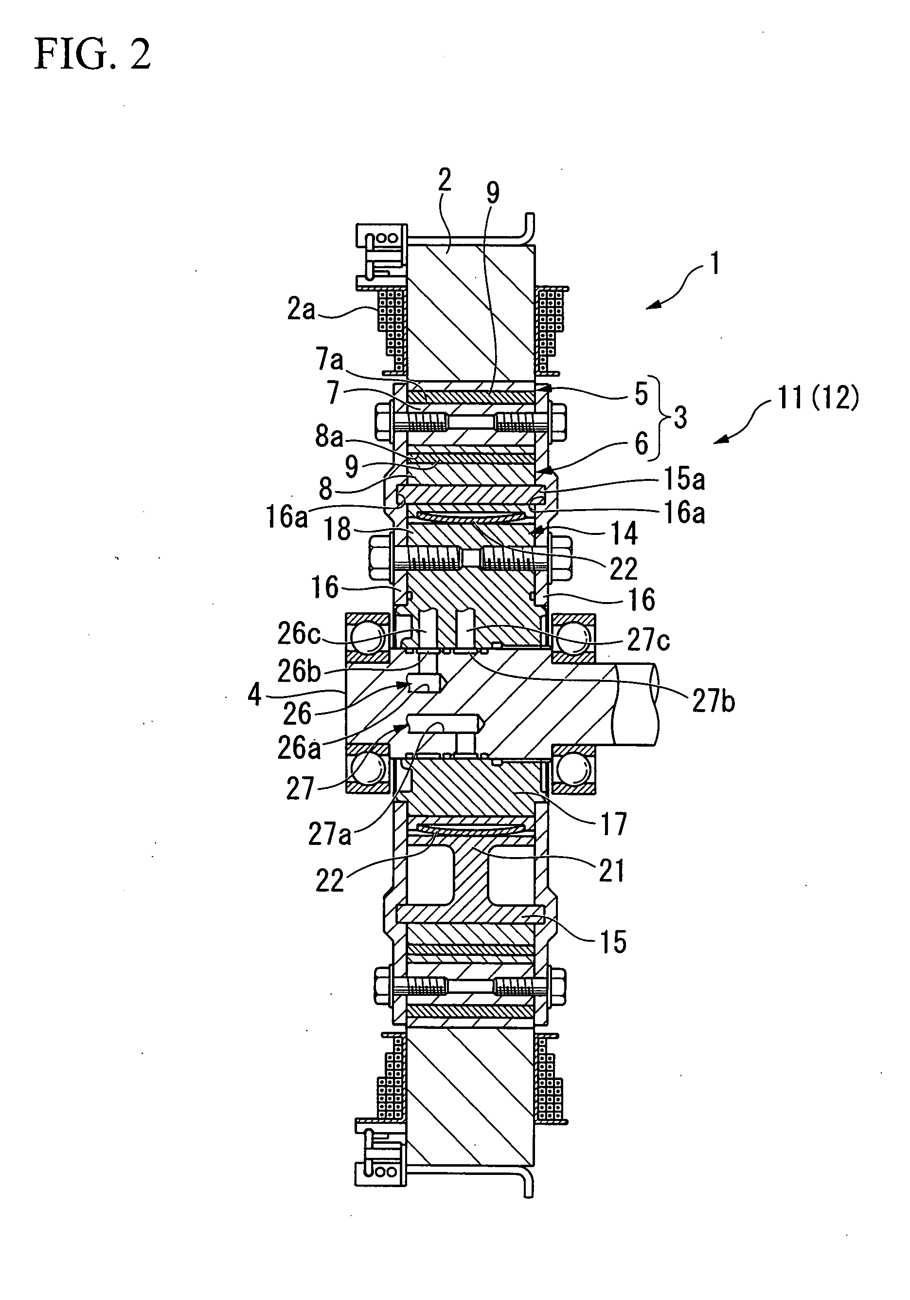
[0022]In this case, it is possible to increase the armature magnetic flux of the weak magnetic field phase that is impressed on the permanent magnet pieces of each rotor member by increasing the induced voltage constant by the phase changing device, and possible to efficiently demagnetize the permanent magnet pieces.

Problems solved by technology

However, in this method, a special apparatus for impressing the high-frequency voltage on the motor is required, and there is the risk that damage may occur due to the temperature of the windings of the motor excessively rising.
For this reason, in the case for example of the battery being degraded, it is not possible to maintain the discharging from the battery, and so there is a possibility of difficulties arising in performing the desired demagnetization.

Method used


Image

  • Motor control method and motor control apparatus
  • Motor control method and motor control apparatus
  • Motor control method and motor control apparatus

Examples


Embodiment Construction

[0034]An embodiment of a motor control method and a motor control apparatus of the present invention will be described below with reference to the appended drawings.

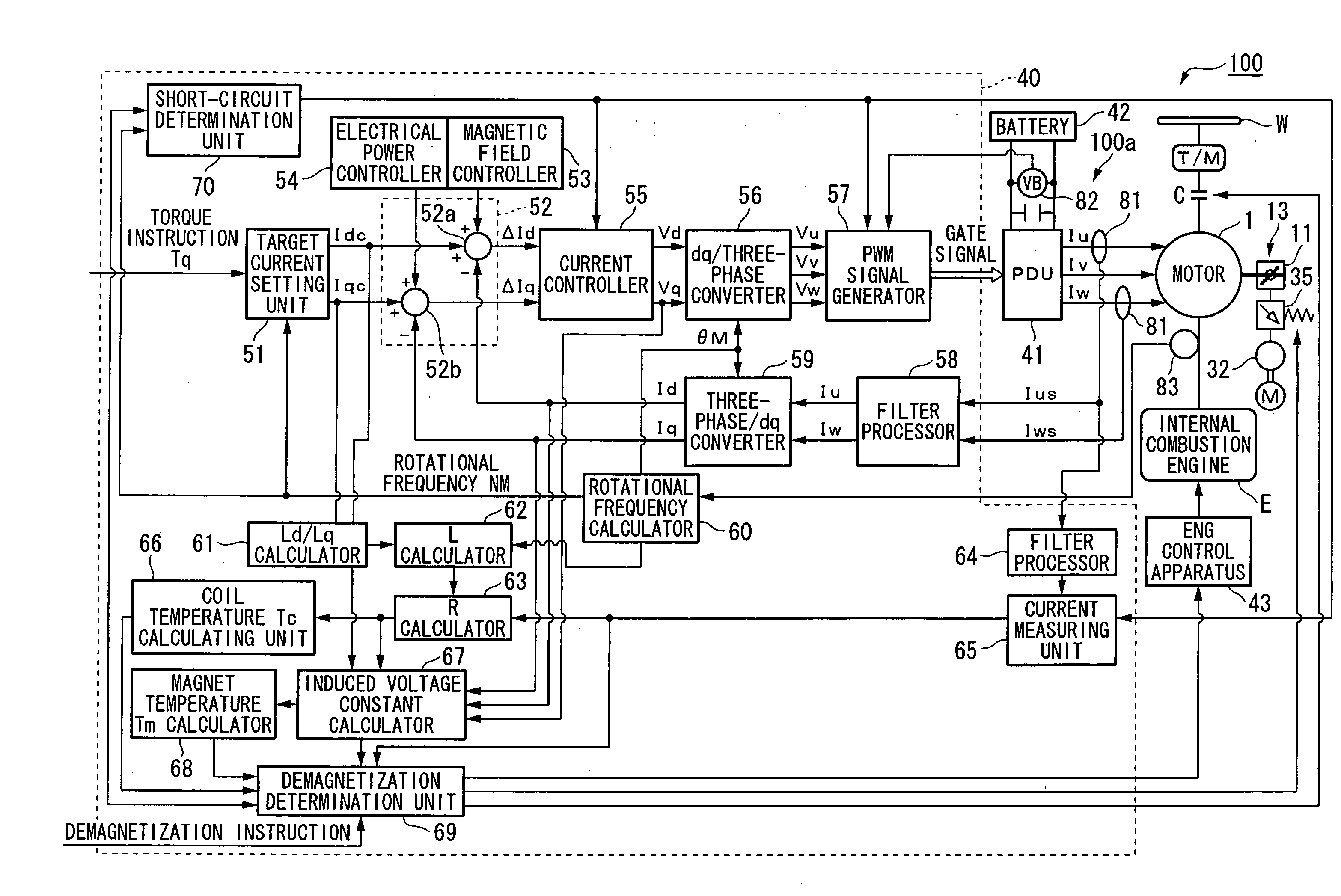
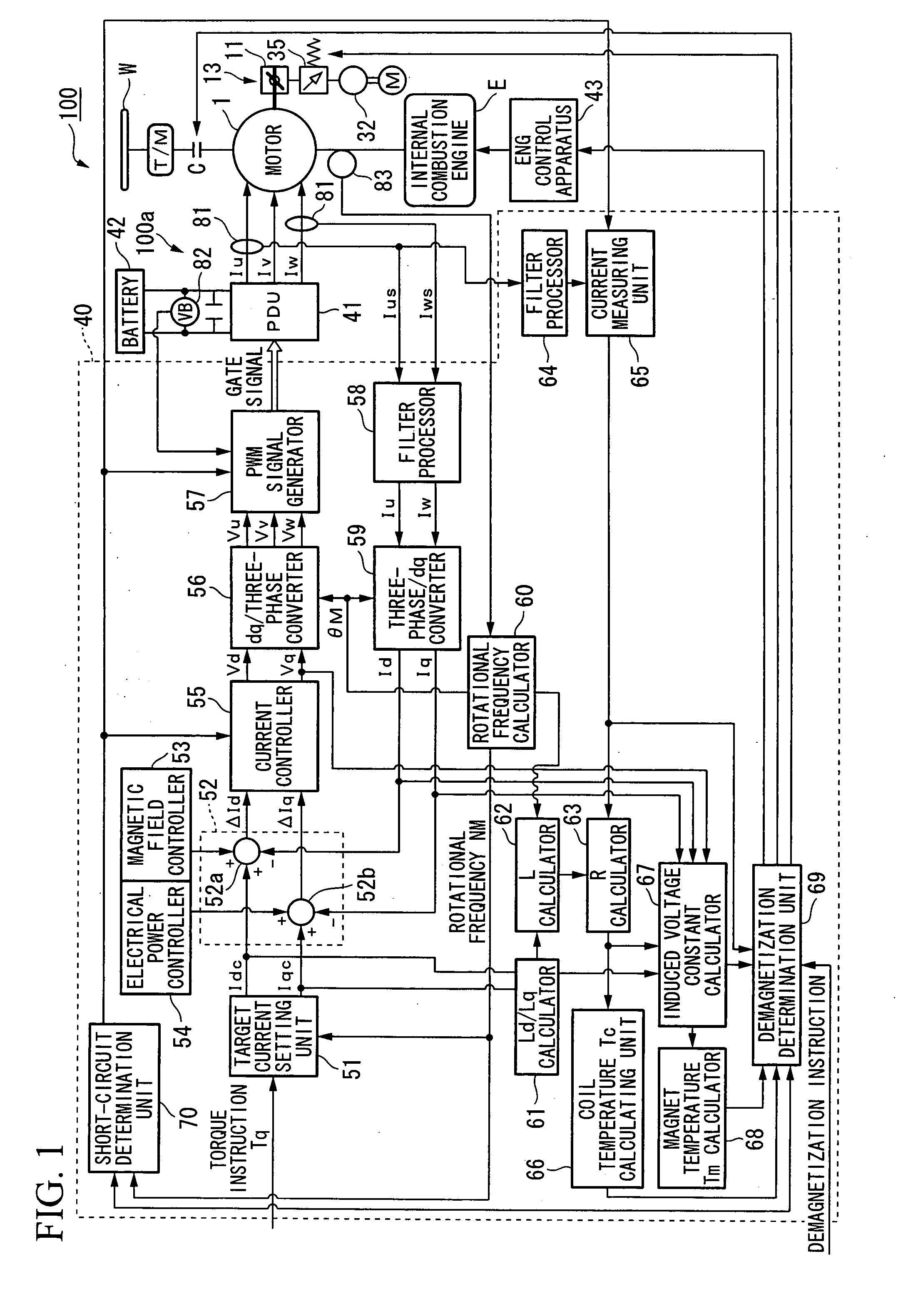
[0035]The motor control apparatus of the present embodiment is mounted as a controller in a vehicle such as a hybrid vehicle or an electric vehicle that is provided with a motor as the traveling driving source. Specifically, as shown in FIG. 1, a vehicle 100 that is mounted with a control apparatus 100a, is a parallel hybrid vehicle that is provided with a motor 1 and an internal combustion engine E as driving sources. The motor 1, the internal combustion engine E and a transmission T / M are connected in series, and at least the drive force of the motor 1 or the internal combustion engine E is transmitted to driving wheels W of the vehicle 100 via a clutch C and the transmission T / M.

[0036]When drive force is transmitted from the driving wheels W side to the motor 1 during deceleration of the vehicle 100, the motor 1, by f...


PUM


Abstract

A motor control method that includes the steps of: rotationally driving a motor that is provided with a rotor having permanent magnet pieces, and a stator; and short circuiting a plurality of phases of the motor when the rotational frequency of the motor is equal to or greater than a predetermined rotational frequency.

Description

[0001]Priority is claimed on Japanese Patent Application No. 2006-325399, filed Dec. 1, 2006, the contents of which are incorporated herein by reference.BACKGROUND OF THE INVENTION[0002]1. Field of the Invention[0003]The present invention relates to a motor control method and a motor control apparatus.[0004]2. Description of Related Art[0005]During disassembly of for example a motor that is equipped with permanent magnets, there is known a conventional method of demagnetizing the permanent magnets by impressing a high-frequency voltage between the terminals of the windings of the motor. (For example, refer to Japanese Unexamined Patent Application, First Publication No. 2001-346364).[0006]However, in this method, a special apparatus for impressing the high-frequency voltage on the motor is required, and there is the risk that damage may occur due to the temperature of the windings of the motor excessively rising.[0007]To address such problems, for a hybrid vehicle that is convention...

Claims


Application Information

Patent Timeline
IPC IPC(8): H02P25/16B60K6/26B60K6/48B60K6/547B60L50/16B60W10/00B60W10/02B60W10/06B60W10/08B60W20/00B60W20/10H02P6/06H02P6/08
CPCH02P6/00B60L15/025B60L2220/14B60L2220/16B60L2220/50B60L2240/425B60L2240/427B60L2240/429B60L2240/441B60L2270/40B60L50/15Y02T10/64Y02T10/7072Y02T10/70
Inventor ATARASHI, HIROFUMIISEGAWA, HIROYUKI
Owner HONDA MOTOR CO LTD
Learn More