
Three-Dimensional Measuring Apparatus, Three-Dimensional Measuring Method, And Three-Dimensional Measuring Program

Active Publication Date: 2008-06-05
FUKUOKA INSTITUTE OF TECHNOLOGY
View PDF11 Cites 51 Cited by
  • Summary
  • Abstract
  • Description
  • Claims
  • Application Information

AI Technical Summary

Benefits of technology

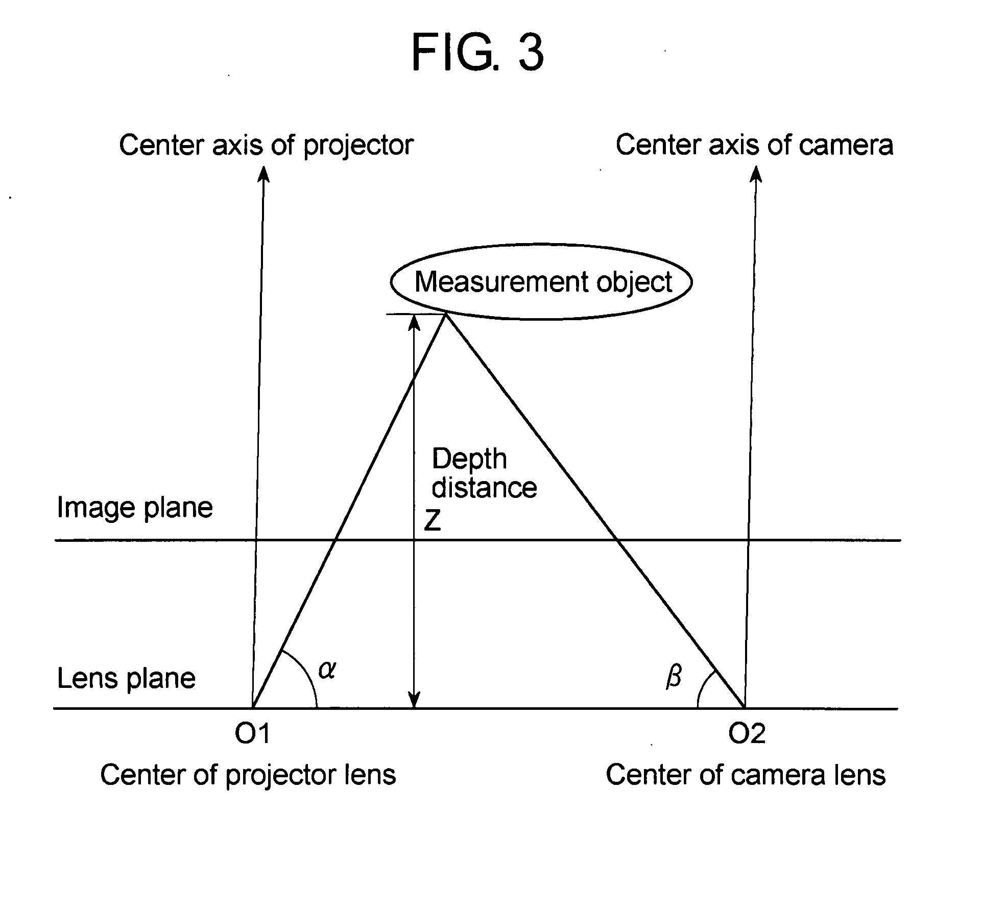
[0020](1) The pattern of light formed by the pattern forming means is projected onto a measurement object by the projecting means, an image of the measurement object illuminated with the pattern of light is captured by the imaging means, and a projected pattern of light is detected on this image by the projected pattern light detection means. It is thus possible to obtain many pieces of information on a projected pattern of light by a single projection. Additionally, the direction angle computing means computes the direction angle of each individual pattern of light in the projected pattern of light, and the dividing means divides the projected pattern of light at every cycle. The phase value computing means computes the phase value at each measuring point of an individual pattern of light or a divided projected pattern of light, and the computed phase value at each measuring point is converted into the depth distance of each measuring point. It is thus possible to obtain three-dimensional information not only on one measuring point, at which the intensity distribution of each individual pattern of light in the projected pattern of light takes on a relative maximum, but also on each measuring point of an individual pattern of light. Thus, highly accurate three-dimensional information can be provided.
(2) The combined pattern of optimum intensity created by the optimum pattern forming means is a pattern of light with a high intensity distribution that maximizes the difference in intensity between each of the relative maximums of an individual pattern of interest and an adjacent individual pattern. Accordingly, the combined pattern of light of optimum intensity projected onto the measurement object allows a projected pattern of light obtained from an image of the measurement object captured by the imaging means to provide the maximized difference in intensity between each of the relative maximums of the individual pattern of light of interest and the adjacent individual pattern of light. It is thus possible to compute the direction angle of an individual pattern of light with improved accuracy and divide the projected pattern of light at every cycle with high accuracy. Accordingly, it is possible to make three-dimensional measurements with further improved accuracy.
(3) The intensity value correcting means corrects the intensity value of the projected pattern of light detected by the projected pattern light detection means. This allows for performing three-dimensional measurements in a short time with high accuracy even on a measurement object whose color distribution or surface reflection property is not clear.
(4) The position correcting means corrects the position of a measurement object in an image acquired by the imaging means. This makes it possible to make three-dimensional measurements in a short time with high accuracy even on a measurement object other than a stationary object.
(5) The three-dimensional information computing means computes the spatial coordinates, distance, angle, area, or volume of a measurement object, and thus various pieces of information on the measurement object can be obtained.
[0021](6) Since the pattern that is used with the three-dimensional measuring apparatus of the present invention is formed in the shape of stripes. It is thus possible to readily analyze, as a sine wave, the intensity distribution of a projected pattern of light used for analysis.

Problems solved by technology

However, because laser light is likely to have adverse effects on the human body, these methods are difficult to apply to the human body.
However, a reduction in the intensity of laser light, in turn, requires an increase in the time of exposure to it, thereby resulting in the total amount of laser light being increased.

Method used


Image

  • Three-Dimensional Measuring Apparatus, Three-Dimensional Measuring Method, And Three-Dimensional Measuring Program
  • Three-Dimensional Measuring Apparatus, Three-Dimensional Measuring Method, And Three-Dimensional Measuring Program
  • Three-Dimensional Measuring Apparatus, Three-Dimensional Measuring Method, And Three-Dimensional Measuring Program

Examples


implementation example

[0097]Now, those results that were obtained by three-dimensional measurements of a human body using the three-dimensional measuring apparatus of the present invention are shown in FIG. 9A to FIG. 9F. FIG. 9A shows an image illuminated with the initial pattern of light, FIG. 9B shows a combined pattern of optimum intensity, FIG. 9C shows an image illuminated with a combined pattern of light of optimum intensity, FIG. 9D shows an image with its intensity value corrected, FIG. 9E shows an image indicating the computed results of depth distances, and FIG. 9F is an image showing a graphical representation of three-dimensional information.

[0098]As shown inFIGS. 9A to 9F, good results were obtained in the three-dimensional measurements of a human body using the three-dimensional measuring apparatus of the present invention. The accuracy of three-dimensional measurement of the present invention depends on the calibration of the measurement system. However, since the recognition rate of the ...


PUM


Abstract

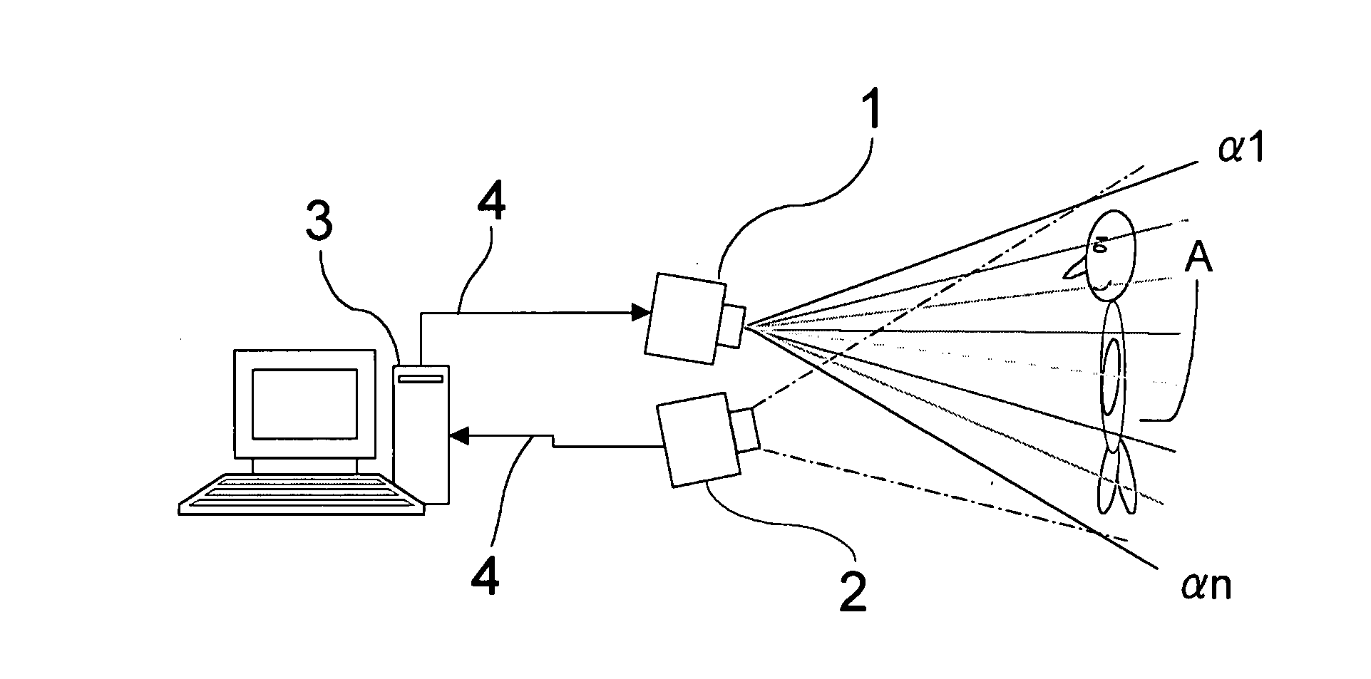
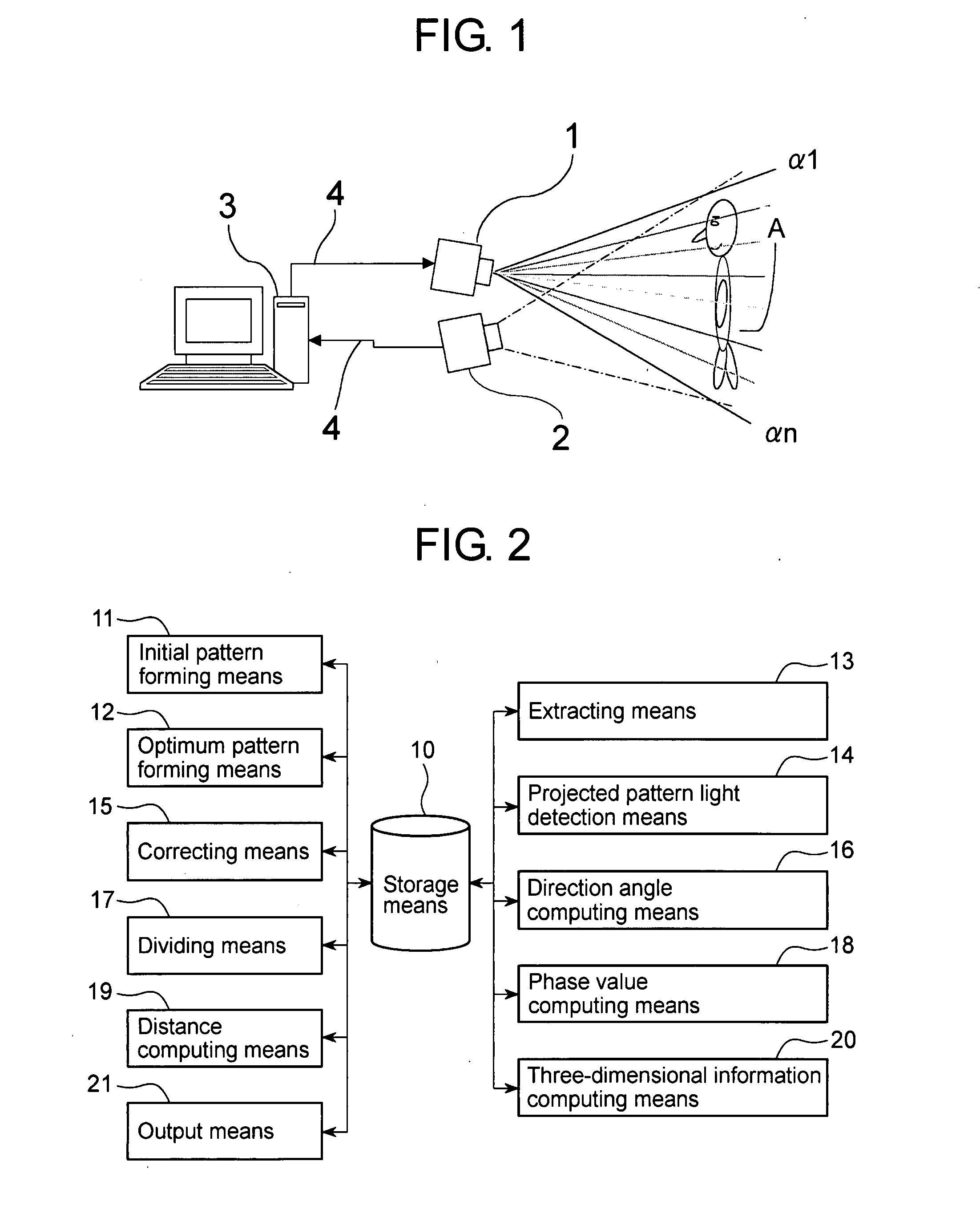
A three-dimensional measuring apparatus, method, and program for acquiring many pieces of information on a pattern of light by a single projection and highly accurate three-dimensional information at high speed. The three-dimensional measuring apparatus comprises a pattern projector (1) serving as projecting means for projecting a pattern of light onto a measurement object (A), a camera (2) serving as imaging means for capturing an image of the measurement object (A) illuminated with the pattern of light, and a computer (3) for processing data on the image captured by the camera (2). The computer (3) computes the direction angle of each individual pattern of light which forms the projected pattern of light from the intensity value of the projected pattern of light detected from the captured image, divides the intensity distribution, and computes the depth distance from the phase value at each measuring point of the divided pattern. Thus, highly accurate three-dimensional information is acquired.

Description

TECHNICAL FIELD[0001]The present invention relates to a three-dimensional measuring apparatus, method, and program for projecting a predetermined pattern of light onto an object for non-contact measurement of three-dimensional information.BACKGROUND ART[0002]In a variety of fields such as medical care, beauty care, apparel design of clothes as well as shoes, eye glasses, or hats, diet control, and health care, in recent years there have been demands for acquiring three-dimensional shape data not only regarding the torso but also regarding the entire human body including the face, the head and the limbs. Thus, expectations are placed on the development of an apparatus for non-contact high-speed measurements of three-dimensional shapes.[0003]Three-dimensional measurement techniques are divided into two types: a passive type for making measurements without illuminating a measurement object with specific light or radio waves serving as an aid for measurement, and an active type for illu...

Claims


Application Information

Patent Timeline
IPC IPC(8): G01B11/03G06V10/145
CPCG01B11/25G06K9/2036G06K9/00369G06V40/103G06V10/145
Inventor LU, CUNWEI
Owner FUKUOKA INSTITUTE OF TECHNOLOGY
Learn More