
Data transmitting apparatus, data receiving apparatus, and data communication system

a data transmitting apparatus and data technology, applied in data switching networks, instruments, frequency-division multiplexes, etc., can solve problems such as affecting the communication performance of the uwb and the cognitive system, affecting the ability of wireless communication of an application, and reducing throughpu

Inactive Publication Date: 2008-06-05
KK TOSHIBA
View PDF8 Cites 323 Cited by
  • Summary
  • Abstract
  • Description
  • Claims
  • Application Information

AI Technical Summary

Benefits of technology

The present invention provides a data transmitting apparatus and a data receiving apparatus that can detect and correct errors in a data transmission. The data transmitting apparatus encodes a packet using two error-correcting methods and generates additional information. The additional information is unique to one of the divided data. The data receiving apparatus separates the blocks of data and performs error-correction decoding on the additional information. If there are errors, the data receiving apparatus sends a request for retransmission to the data transmitting apparatus. The data transmitting apparatus retransmits the data and the receiving apparatus performs error-correction decoding on the retransmitted data. This invention allows for efficient and accurate data transmission and reception.

Problems solved by technology

In this case, however, a wireless communication for an application has a possibility of interfering with a wireless communication for another application.
Although this technology is necessary to protect the licensed system, a sudden transmission stoppage affects communication performance of the UWB and the cognitive system.
However, the retransmission uses a bandwidth for a normal traffic, which reduces throughput.
However, according to the technology disclosed in JP-A 2005-269480 (KOKAI), because relation between each of the divided blocks and the frame is not known at the time of decoding the inner code, the system may request the retransmission of the block of the frame that is not allowed to be retransmitted.
As a result, the transmission efficiency can be reduced.
In such a case, the amount of the retransmission can be reduced by retransmitting only the bursting errors; however, the technology disclosed in JP-A 2005-269480 (KOKAI) also retransmits blocks with non-burst errors such as errored block due to fading, resulting in reduced transmission efficiency.

Method used


Image

  • Data transmitting apparatus, data receiving apparatus, and data communication system
  • Data transmitting apparatus, data receiving apparatus, and data communication system
  • Data transmitting apparatus, data receiving apparatus, and data communication system

Examples


first embodiment

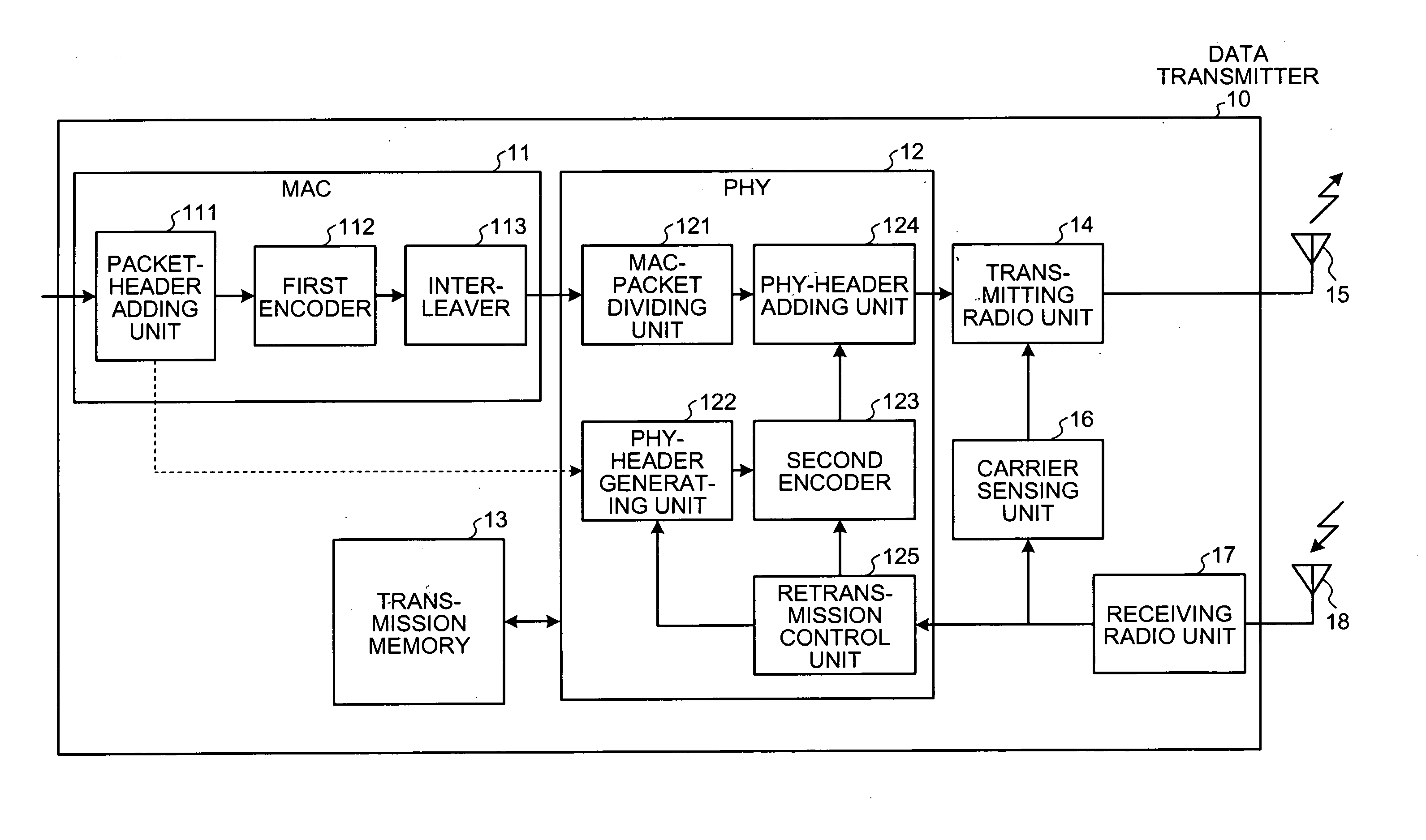
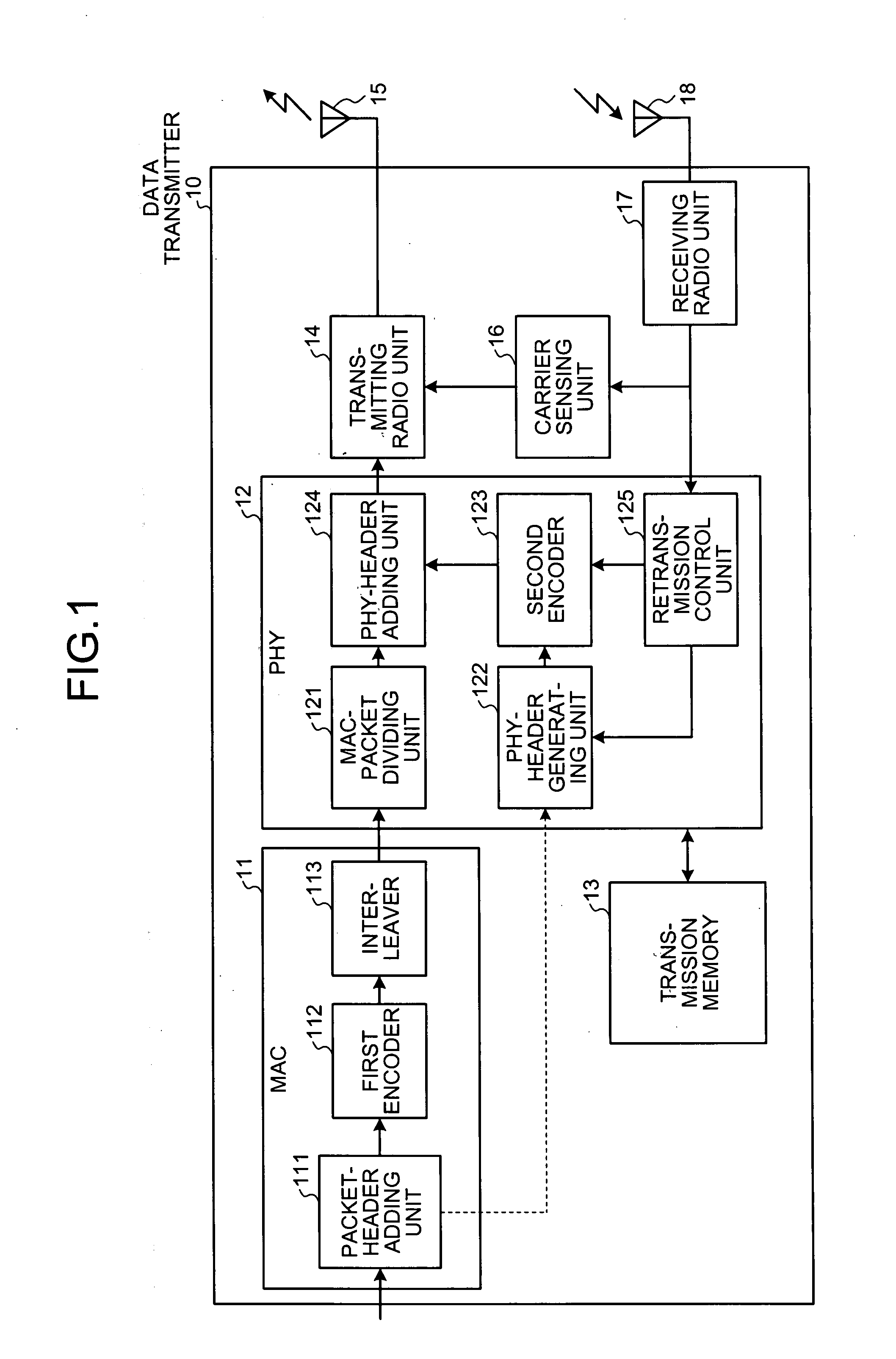
[0025]A data communication system is explained below. The data communication system includes a data transmitter 10 as a data transmitting apparatus and a data receiver 20 as a data receiving apparatus.

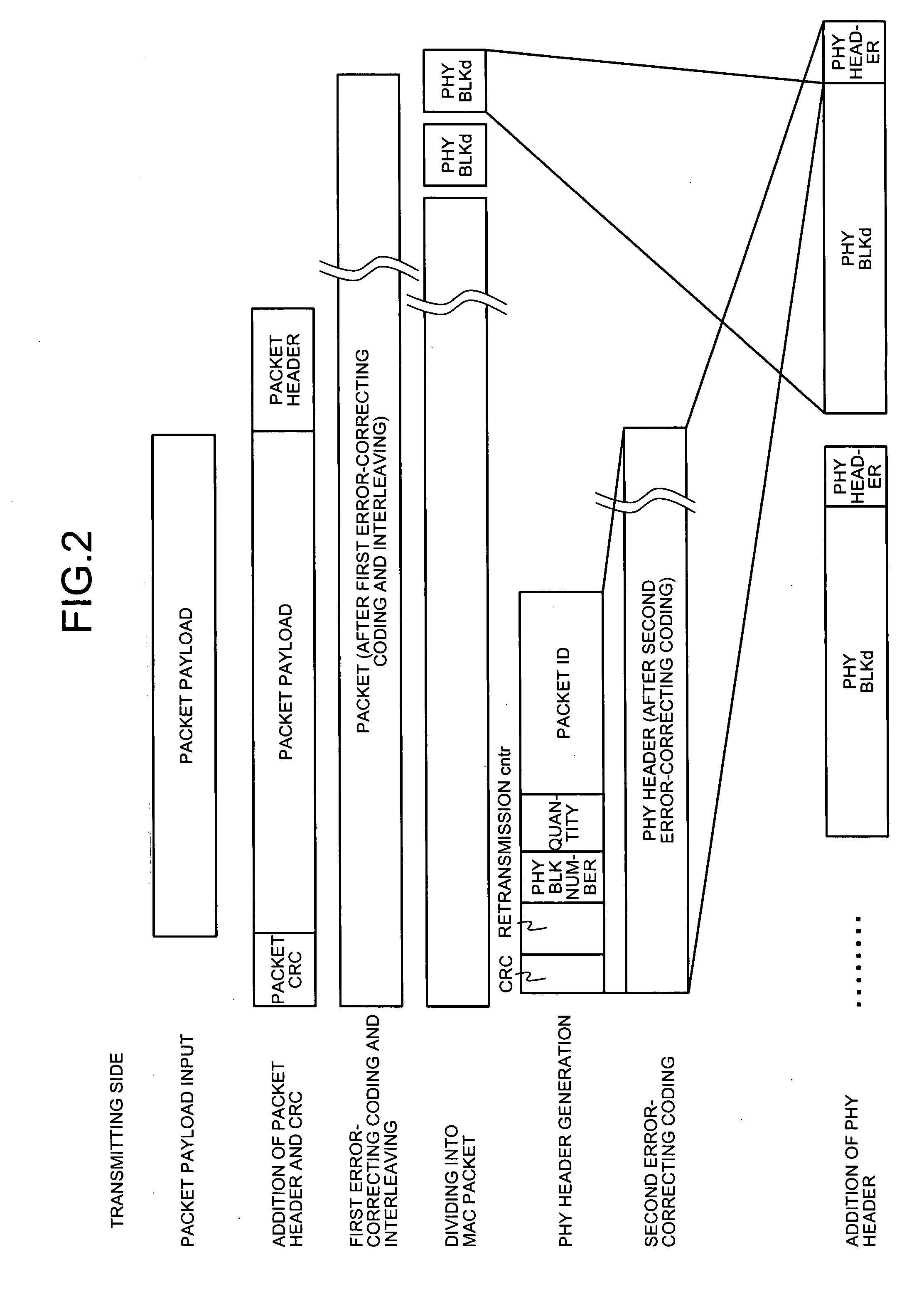
[0026]FIG. 1 is a block diagram of the data transmitter 10. FIG. 2 is a schematic view of operations performed by the data transmitter 10.

[0027]The data transmitter 10 includes a MAC 11 that performs a process in a media access control (MAC) layer, a PHY 12 that performs a process in a physical (PHY) layer, a transmission memory 13, a transmitting radio unit 14, a transmission antenna 15, a carrier sensing unit 16, a receiving radio unit 17, and a reception antenna 18. In the data transmitter 10 according to the first embodiment, data to be transmitted is formed into a packet payload in a data link layer by a data forming unit (not shown), and then the formed data is output to a packet-header adding unit 111to be described later.

[0028]The MAC 11 includes the packet-header adding unit ...

second embodiment

[0139]The retransmission control unit 125 starts counting as soon as the PHY-header adding unit 124 outputs a PHY block, and determines whether a predetermined time has passed, based on the time measured by the timer 19. The retransmission control unit 125 clears the count upon receiving one of an Ack-p and a Nack-p from the data receiver 40.

[0140]As shown in FIG. 11, the data receiver 40 includes a timer 28 that measures time in addition to the configuration of the data receiver 20 shown in FIG. 3.

[0141]The retransmission-count checking unit 235 starts counting upon outputting the information on a PHY block to be retransmitted to the retransmission processing unit 236, and determines whether a predetermined time has passed, based on the time measured by the timer 28. The retransmission-count checking unit 235 clears the count as soon as the PHY block retransmitted from the data transmitter 30 is input.

[0142]In the following, actions performed by the data transmitter 30 and the dat...


PUM


Abstract

A data transmitting apparatus generates a block that includes identification information including the number of times divided data can be transmitted and data for error detection for detecting an error in the identification information associated with each other with respect to each divided data, and transmits the block to a data receiving apparatus. If the number of times divided data can be transmitted is one or more, the data transmitting apparatus stores the corresponding block in a transmission memory, and retransmits it upon a request for retransmission from the data receiving apparatus.

Description

CROSS-REFERENCE TO RELATED APPLICATIONS[0001]This application is based upon and claims the benefit of priority from the prior Japanese Patent Application No. 2006-324229, filed on Nov. 30, 2006; the entire contents of which are incorporated herein by reference.BACKGROUND OF THE INVENTION[0002]1. Field of the Invention[0003]The present invention generally relates to a data transmitting apparatus, a data receiving apparatus, and a data communication system.[0004]2. Description of the Related Art[0005]An increasing number of methods have been used to realize communication in familiar surroundings along with the development of the information society, and the communication speed has remarkably increased. To further increase the communication speed, an acceptable use policy is set for a new medium. In most types of existing wireless communication, a regulation requires that a certain bandwidth should be used only for a predetermined application. However, some of the bandwidths can be use...

Claims


Application Information

Patent Timeline
Patent Type & Authority Applications(United States)
IPC IPC(8): H04B7/00H04L1/16H04L47/43
CPCH04L1/0009H04L1/1819H04L1/0072H04L1/0071
Inventor TOMIOKA, TAZUKO
Owner KK TOSHIBA
Learn More