Permute Unit and Method to Operate a Permute Unit

a permute unit and permute technology, applied in the field of permute units, can solve the problems of inability to double-pump the system, and the power drawback of modern microprocessors, and achieve the effect of reducing the cost of silicon area and power dissipation

Inactive Publication Date: 2008-06-05
IBM CORP
View PDF2 Cites 17 Cited by
  • Summary
  • Abstract
  • Description
  • Claims
  • Application Information

AI Technical Summary

Benefits of technology

[0007]It is therefore an object of at least one embodiment of the invention to provide a permute unit that can be double pumped in order to reduce cost as silicon area and power dissipation plus a method to operate such a permute unit. This object is met by a permute unit comprising a permute logic (20) and a crossbar (41) working in cycles defined by clocking signals and generating one valid output vector (vo) per cycle by treating two parallel input vectors (va, vb) per cycle according to an adequate scheme, characterized...

Problems solved by technology

Modern microprocessors suffer a huge power drawback, where power is a combination of static and dynamic contribution; thereby the static contribution is approximately proportional to the s...

Method used


Image

  • Permute Unit and Method to Operate a Permute Unit
  • Permute Unit and Method to Operate a Permute Unit
  • Permute Unit and Method to Operate a Permute Unit

Examples


Embodiment Construction

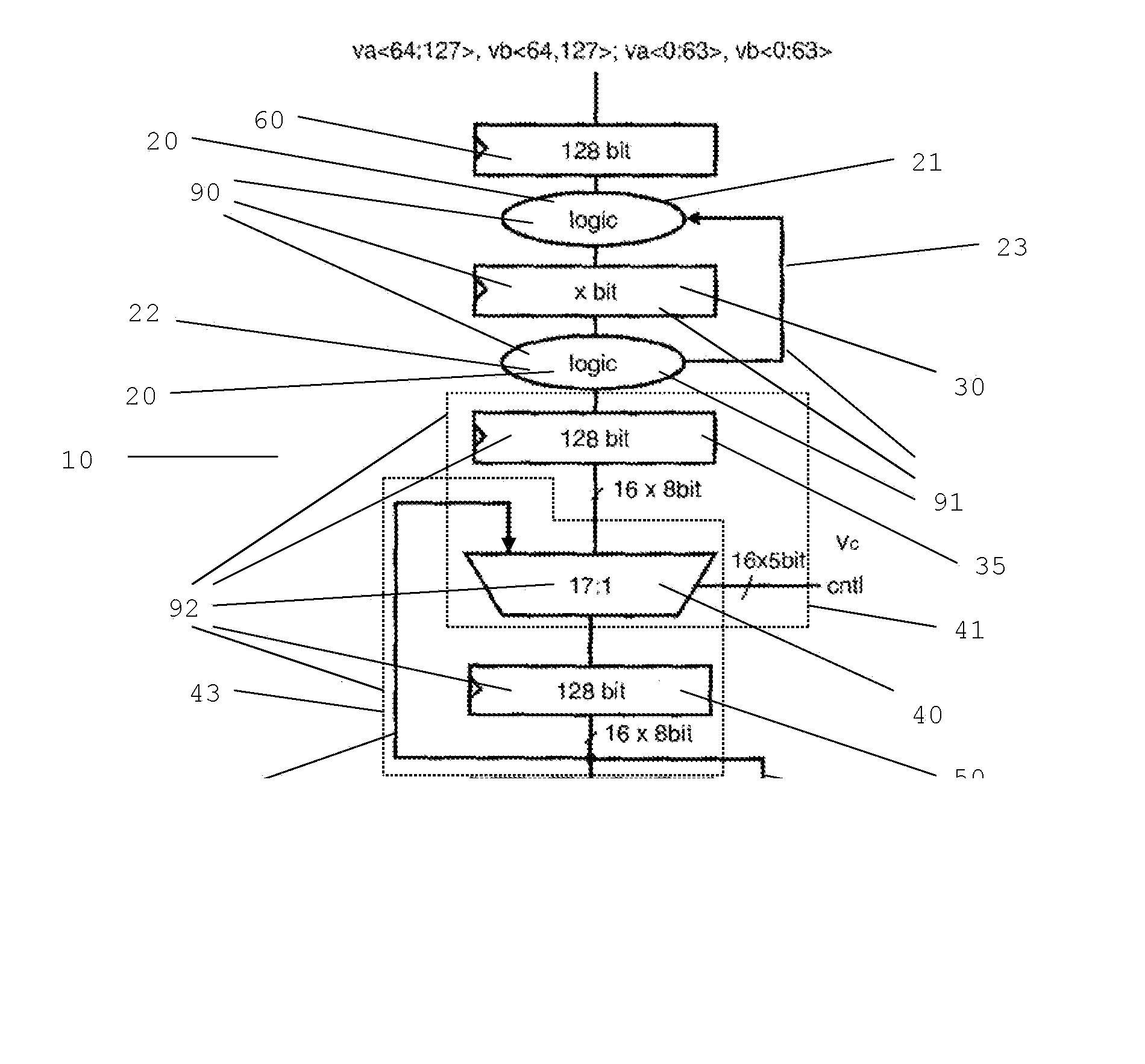
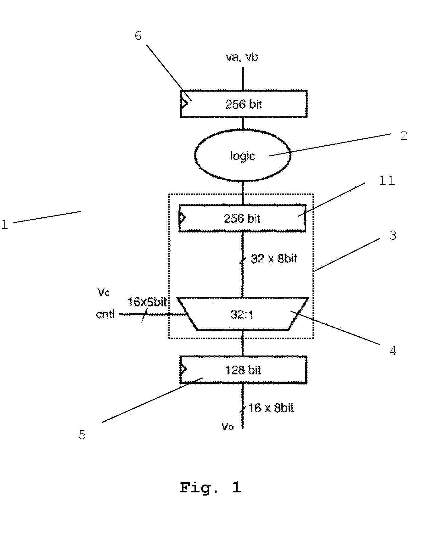
[0026]A permute unit 1 according to the state of the art as shown in FIG. 1 comprises a permute logic 2 and a crossbar 3 working in cycles defined by clocking signals. The permute unit 1 generates one valid output vector vo of 128 bit width per cycle by treating two parallel input vectors va, vb per cycle according to an adequate scheme. The two parallel input vectors va, vb have full width of 128 bit each, resulting in an input register 6 of 256 bit width and a crossbar 3 of also 256 bit width. The permute unit 1 further comprises a multiplexer 4, an output register 5, an input register 6 and an operand staging latch 11. The multiplexer 4 together with the operand staging latch 11 and corresponding interconnections realizes the crossbar 3, which distributes all thirty-two input bytes to all sixteen output bytes. Sixteen times five control signals trigger each of the sixteen 32:1 multiplexers individually to transfer the proper input byte to the result byte.

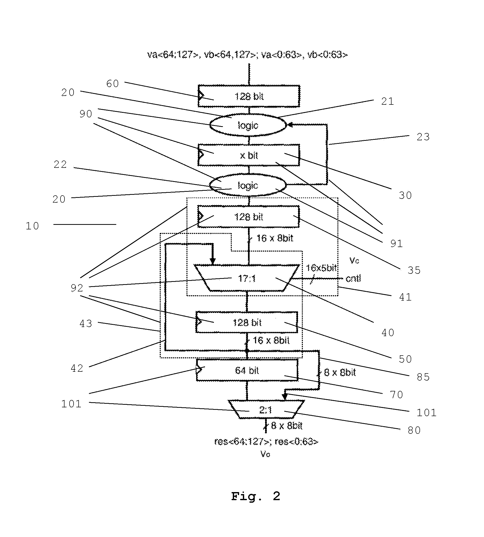
[0027]FIG. 2 shows a doub...


PUM


Abstract

A permute unit is described comprising a permute logic and a crossbar working in cycles defined by clocking signals and generating one valid output vector per cycle by treating two parallel input vectors per cycle according to an adequate scheme, wherein the permute unit is double pumped by performing two inner cycles per outer cycle defined by the clocking signals, wherein in every first inner cycle first halves of both input vectors are treated and in every second inner cycle second halves of both input vectors are treated and wherein every second inner cycle a valid output vector is generated from the results of the treatments within the first and the second inner cycles. Furthermore a method is described to operate such a permute unit.

Description

BACKGROUND OF THE INVENTION[0001]The invention relates to a permute unit comprising a permute logic and a crossbar working in cycles defined by clocking signals and generating one valid output vector per cycle by treating two parallel input vectors per cycle according to an adequate scheme, plus a method to operate such a permute unit.[0002]Modern microprocessors suffer a huge power drawback, where power is a combination of static and dynamic contribution; thereby the static contribution is approximately proportional to the silicon areas of a macro.[0003]To reduce area within a microprocessor, i.e., to reduce cost of silicon area and leakage power, double pumping is frequently used. When double pumping is applied to a unit within a microprocessor, it operates twice as fast as the incoming datarate. This is typically achieved in adding additional register boundaries in the middle of a cycle. Assuming doubling of the clock frequency and identical wordlength, such a double pumped unit ...

Claims


Application Information

Patent Timeline
IPC IPC(8): H04L9/28
CPCG06F13/4217Y02B60/1235Y02B60/1228Y02D10/00
Inventor GEMMEKE, TOBIASLEENSTRA, JENSWENDEL, DIETER
Owner IBM CORP
Why Eureka
Try Eureka