
Sound field reproduction system

a technology of sound field and reproduction system, which is applied in the direction of transducer details, stereophonic arrangments, signal processing, etc., can solve the problems of system design, sound leakage from driver seat speakers may disturb other occupants, and have not been designed

Active Publication Date: 2008-06-05
FUJITSU GENERAL LTD
View PDF9 Cites 54 Cited by
  • Summary
  • Abstract
  • Description
  • Claims
  • Application Information

AI Technical Summary

Benefits of technology

[0009]Accordingly, it is an object of the present invention to provide a sound field reproduction system that can solve the above problems.
[0010]It is another object of the present invention to provide a sound field reproduction system that can enhance the sound separation between the front and rear seats or left and right seats of a vehicle.
[0011]It is a further object of the present invention to provide a sound field reproduction system that allows the occupant of each seat inside a vehicle to listen to an independent sound source in a good condition.
[0014]According to the sound field reproduction system of the present invention, the occupants of the front and rear seats of the vehicle can listen to different sound sources and / or music sources without the sound sources interfering with each other.
[0015]Further, according to the sound field reproduction system of the present invention, the sound and / or music corresponding to the first display image and the second display image simultaneously displayed on the display unit can be enjoyed at the passenger seat and the driver seat without the sound sources interfering with each other.

Problems solved by technology

However, since the sounds from the usual four speakers mounted in the four door panels can also be heard by the driver, there has been the problem that the sounds may become distracting to the driver when the driver is listening to route guidance and traffic congestion information from the navigation system, while on the other hand, sound leakage from the driver seat speakers may disturb the other occupants who are listening to music being played back on a CD player.
However, the above system has not been designed by taking into consideration the environment inside a vehicle, nor has it been a system designed for use in any specific frequency range of the sound output signal.

Method used


Image

  • Sound field reproduction system
  • Sound field reproduction system
  • Sound field reproduction system

Examples


Embodiment Construction

[0033]A sound field reproduction system according to the present invention will be described below with reference to the drawings. However, it should be noted that the scope of the present invention is not limited by the specific embodiments described herein, but may be defined by the appended claims and their equivalents.

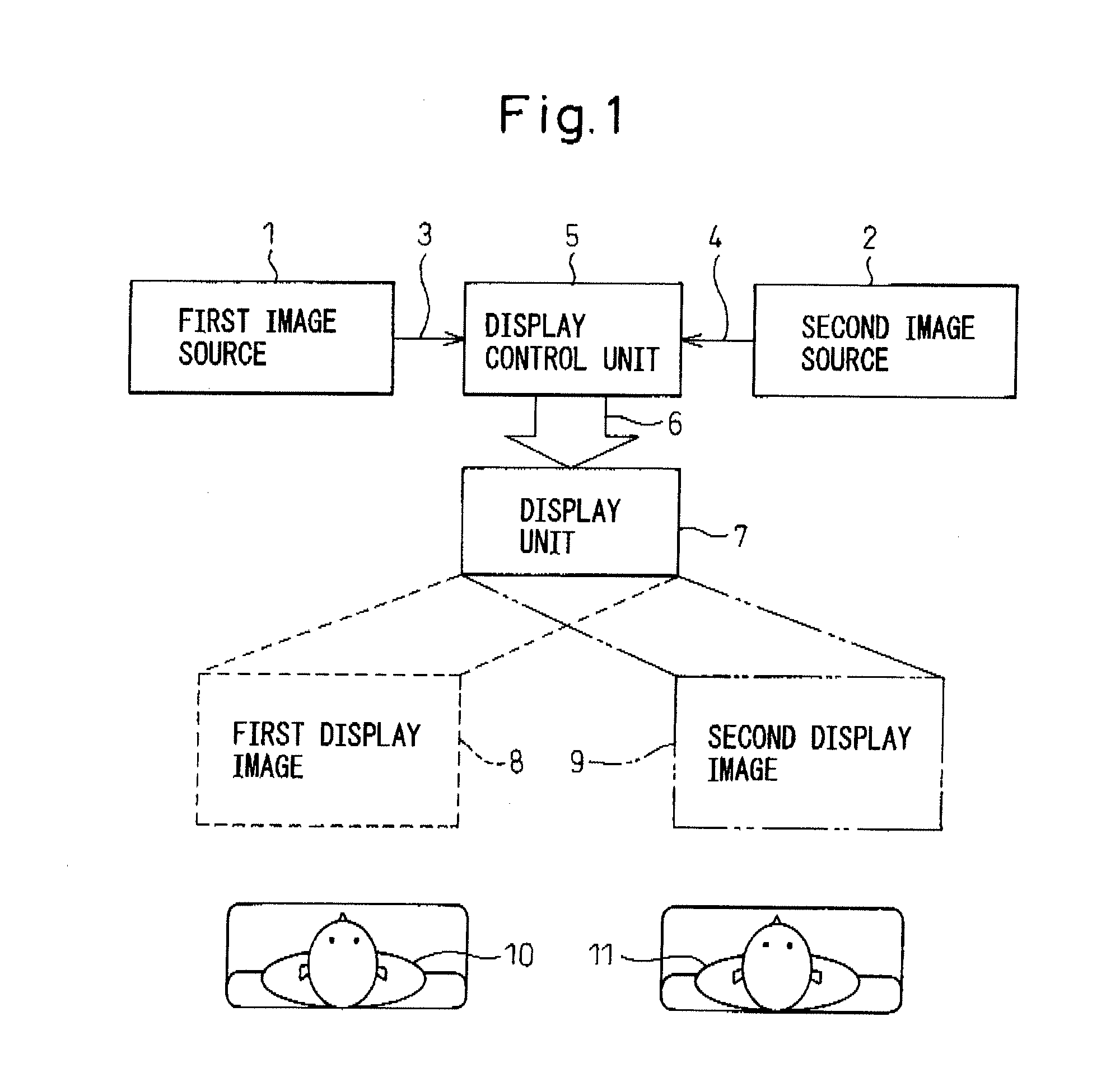
[0034]FIG. 1 is a conceptual diagram of a display device. In the figure, reference numeral 1 is a first image source, 2 is a second image source, 3 is first image data from the first image source, 4 is second image data from the second image source, 5 is a display control unit, 6 is display data, 7 is a display unit (constructed, for example, from a liquid crystal panel or the like), 8 is a first display image based on first image source 1, 9 is a second display image based on second image source 2, 10 is an observer (user) located to the left relative to the display unit 7, and 11 is an observer (user) located to the right relative to the display unit 7.

[0035]The ...


PUM


Abstract

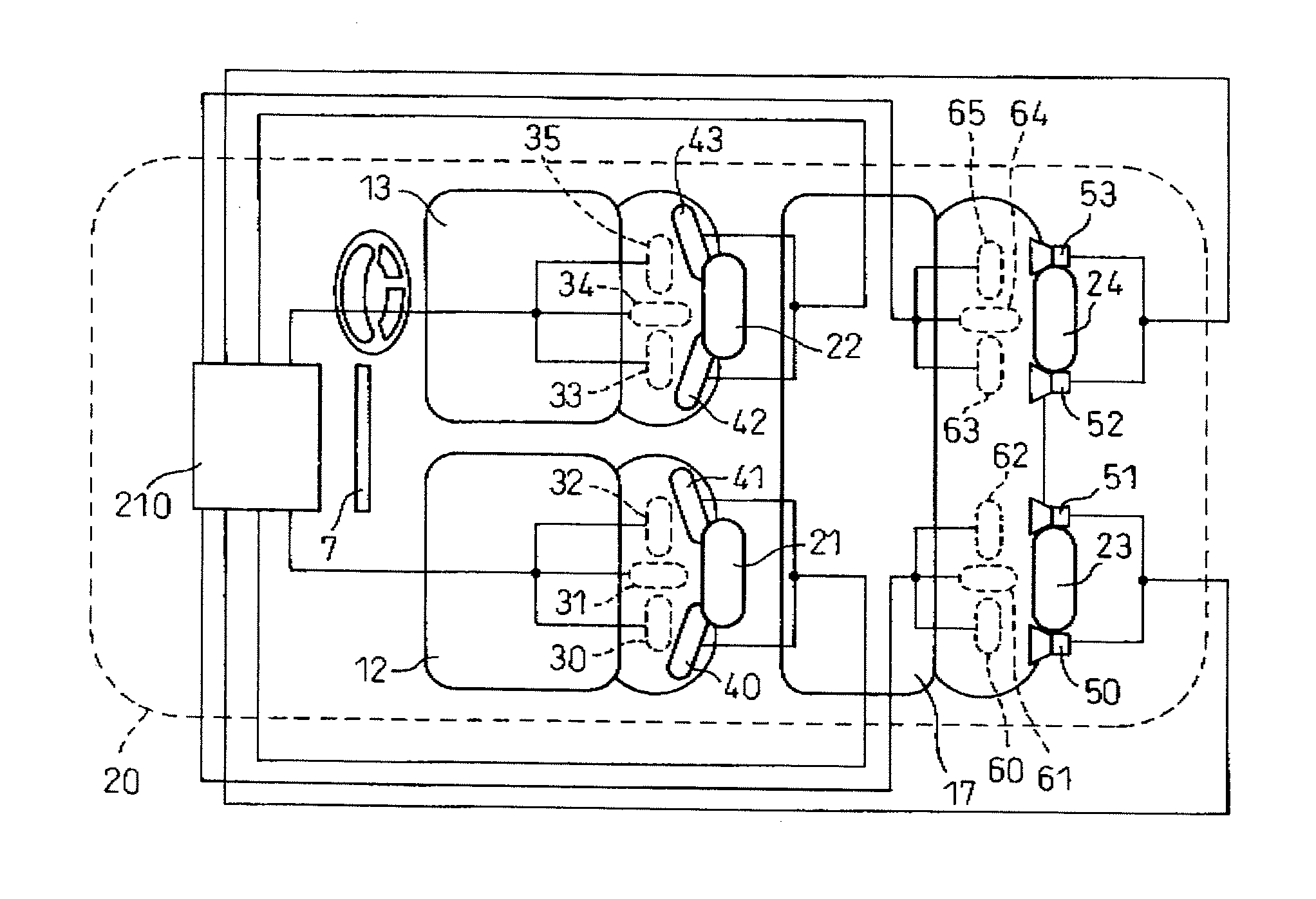
The present invention is directed to providing a sound field reproduction system that can enhance the sound separation between the front and rear seats or left and right seats of a vehicle. The sound field reproduction system includes a control unit for creating a first sound signal and a second sound signal from one or a plurality of sources, a narrow-directional speaker mounted on the front seat side of the vehicle, a speaker mounted on the rear seat side of the vehicle, and a signal processing unit for driving the narrow-directional speaker based on the first sound signal that has been processed according to frequency range, and for driving the speaker based on the second sound signal.

Description

[0001]This application is a new U.S. patent application that claims benefit of JP 2006-325479, filed on Dec. 1, 2006, the entire content of JP 2006-325479 is hereby incorporated by reference.FIELD OF THE INVENTION[0002]The present invention relates to a sound field reproduction system, and more specifically to a personal sound field reproduction system that allows a plurality of people sitting near each other to listen to different sound sources.BACKGROUND OF THE INVENTION[0003]It is known to provide an automotive audio system in which, in addition to four speakers being mounted in four door panels, speakers for the vehicle driver are mounted in the headrest of the driver seat so that only the driver can listen to route guidance and traffic congestion information from the navigation system, while allowing other vehicle occupants other than the driver to listen to music being played back on a CD player (refer, for example, to patent document 1).[0004]However, since the sounds from th...

Claims


Application Information

Patent Timeline
IPC IPC(8): H04R5/02H04S1/00
CPCH04R1/403H04R3/12H04S1/002H04R2430/20H04R5/023H04R2499/13
Inventor SHIBATA, KIYOSEIMAEDA, MASANOBU
Owner FUJITSU GENERAL LTD
Learn More