
Tunnel dressing for use with negative pressure wound therapy system

a technology of negative pressure and tunnel dressing, applied in the field of tunnel dressing, can solve the problems of difficult dressing placement, difficult to heal completely, and significant infection risks, and achieve the effect of sufficient tensile strength

Inactive Publication Date: 2008-06-05
PAUL HARTMANN AG
View PDF19 Cites 95 Cited by
  • Summary
  • Abstract
  • Description
  • Claims
  • Application Information

AI Technical Summary

Benefits of technology

[0016]A tunnel dressing for treating a wound with suction comprising a generally elongate permeable member is provided. The permeable member comprises a distal end; a proximal end; a cohesive permeable outer wound contact surface; and a permeable internal core. The wound contact surface is adapted to transport wound exudates from the wound tissue to the internal core and is generally free of protrusions that could become embedded in the wound tissue and left behind in the wound tissue when the tunnel dressing is remove

Problems solved by technology

Because of their depth, tunneling wounds can present significant risks of infection and can be particularly difficult to heal completely.
Poor healing in the deepest portions of a wound can lead to abscesses if the shallower portion of the wound heals first and closes off the tunnel.
A challenge in treating tunneling wounds with suction is that it can be difficult to place a dressing into a deep tunneling wound so that the dressing can effectively facilitate the removal of wound exudates.
Another challenge in treating tunneling wounds with suction arises because the application of vacuum causes intimate contact between tissue and dressing materials, which can cause the tunnel dressing materials to stick to or become entangled with the wound surface.
Entanglement or sticking of the dressing to the wound tissue creates a risk that pieces of the dressing can be broken off and left in the wound when the dressing is removed, and because the tunneling wound is deep, these pieces are not detectable by the clinician removing the dressing.
Entanglement or sticking of the dressing to the wound tissue can also cause considerable pain to a patient when the dressing is removed.
There are several disadvantages to these types of devices.
Because these devices are constructed from an impermeable material having discrete holes, vacuum cannot be applied uniformly and is thus concentrated on a relatively small portion of the wound surface.
Further, the material from which these devices are formed is relatively inflexible, making it difficult and uncomfortable for the patient when the devices are inserted into a wound.
Still further, the presence of discrete holes provides space into which large protrusions of tissue can grow, which can cause considerable pain when the devices are removed from a wound.
A disadvantage of using foam is that foam lacks any significant tensile strength and thus is prone to break when being extracted from the wound, leaving pieces behind within the tunneling wound cavity.
Moreover, it is not possible to readily discern when a piece of foam has broken off and remains lodged in the wound, because a torn or cut edge of the foam appears the same as a broken edge.
A further disadvantage of foam is that the foam lacks the stiffness required to push it into many tunneling wounds, so that a clinician often must use a long Q-tip or other ad hoc device to help push the foam dressing into the wound.
Numerous disadvantages result from this type of arrangement.
Thus, the applied suction will generally be able to evacuate exudates from a wound but will be unable to apply suction forces to tissue that is in contact with only the tube.
Still further, when the pad is made from foam, all of the problems discussed above with regard to foam dressings may result.
Also, there is no mechanism for introducing the device into a deep tunnel wound other than by pushing on the flexible tube.

Method used


Image

  • Tunnel dressing for use with negative pressure wound therapy system
  • Tunnel dressing for use with negative pressure wound therapy system
  • Tunnel dressing for use with negative pressure wound therapy system

Examples


Embodiment Construction

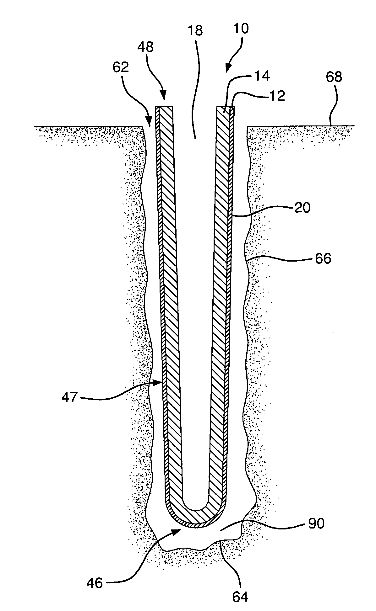
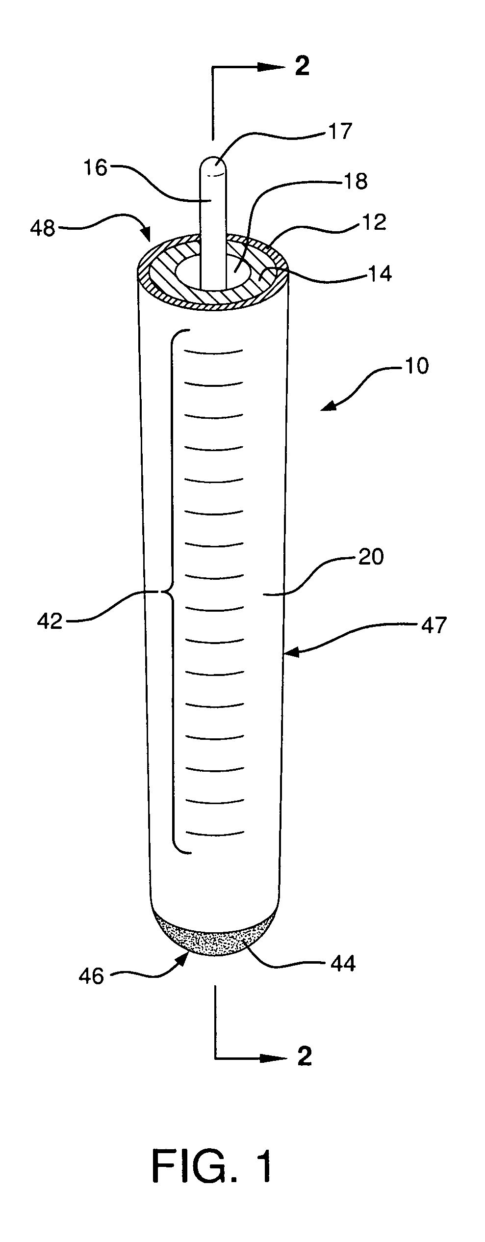
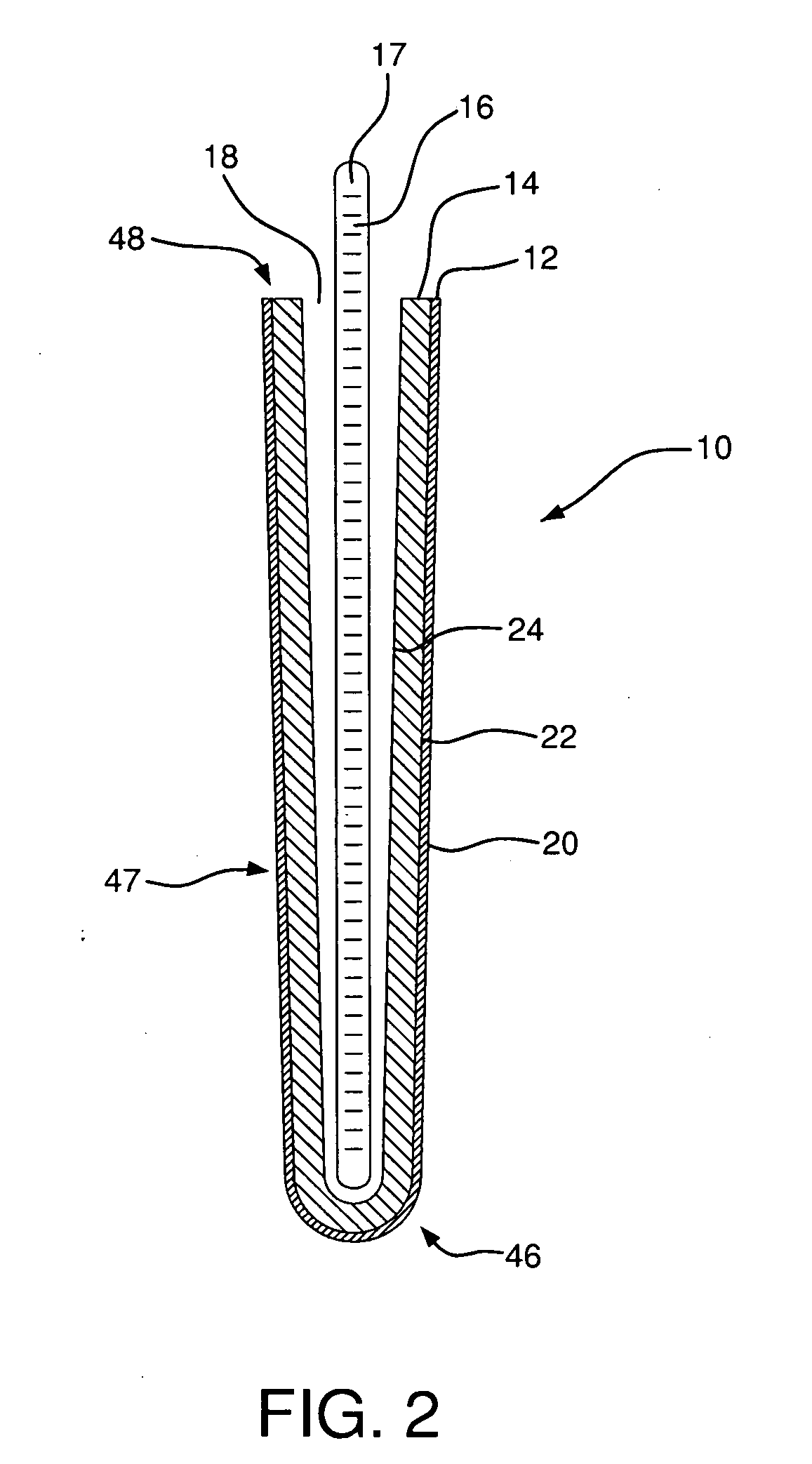
[0029]Referring to the drawings, where like numerals identify like elements, there is shown in FIGS. 1 and 2 a tunnel dressing 10 for treating a tunneling wound with suction according to an embodiment of the invention. The tunnel dressing 10 has a generally elongate shape to provide for insertion of the tunnel dressing 10 into a tunneling wound, such as shown in FIGS. 3A and 3B. The tunnel dressing 10 preferably has a closed distal end 46 and an open proximal end 48, and sides 47 spanning between the ends 46, 48, such that the closed end 46 can be inserted into a tunneling wound with the open end 48 protruding outwardly from the wound. The tunnel dressing 10 can have a generally round or circular cross-section, as shown in FIG. 1, or can have a more oblong or ovalized cross-section, depending on the shape of the tunneling wound into which the tunnel dressing 10 will be inserted. The tunnel dressing 10 can be used, as illustrated for example in FIGS. 7A and 7B, for treating a tunneli...


PUM


Abstract

A tunnel dressing for use in treating a tunneling wound using negative pressure wound therapy. The tunnel dressing includes an elongate permeable member having a closed distal end for entering the wound and an open proximal end into which an applicator is removably disposed for guiding the dressing into the wound. The tunnel dressing has a support structure adapted to transport wound exudates away from the wound and to resist compression under suction. The tunnel dressing also has a wound contact surface adapted to minimize tissue entanglement to facilitate removal. The support structure and wound contact surface may be formed from the same material or from two adjacent layers of different material.

Description

REFERENCE TO RELATED APPLICATIONS[0001]This application claims the priority of U.S. Provisional Application No. 60 / 861,358 filed Nov. 28, 2006.FIELD OF THE INVENTION[0002]The present invention relates to the treatment of tunneling wounds using suction or negative pressure wound therapy. More particularly, the present invention relates to dressings for use in treating tunneling wounds with suction.BACKGROUND OF THE INVENTION[0003]When treating wounds, occasionally wounds are encountered that are best described as “tunneling” wounds. A tunneling wound is substantially tunnel-shaped, having an opening at the surface and extending into the flesh, forming a tunnel that is usually longer, and sometimes substantially longer, than the width of the opening. Tunneling wounds can occur by themselves or in combination with a larger open wound, which may include one or more tunneling wounds. Because of their depth, tunneling wounds can present significant risks of infection and can be particular...

Claims


Application Information

Patent Timeline
IPC IPC(8): A61F13/02A61F13/00
CPCA61F13/00021Y10T156/108A61F13/00068A61F13/00085A61F13/00995A61F13/023A61F15/005A61F2013/00093A61F2013/00174A61F2013/00302A61F2013/00536A61F2013/0054A61F2013/00561A61F2013/00825A61M1/0088A61M27/00A61F13/00059A61M1/962A61M1/916A61M1/915A61F13/01021A61F13/05
Inventor RADL, CHRISTOPHER L.KLOCEK, KEVIN P.KARPOWICZ, JOHN
Owner PAUL HARTMANN AG
Learn More