Modular long bone prosthesis

a long bone, modular technology, applied in the field of prosthesis, can solve the problems of not being able to tailor the prosthesis effectively, cost-effective and efficient, and not being able to accommodate significant differences between patients, so as to reduce the risk of aseptic loosening, and optimise the osseointegration of the par

Inactive Publication Date: 2008-06-05
STANMORE IMPLANTS WORLDWIDE
View PDF7 Cites 36 Cited by
  • Summary
  • Abstract
  • Description
  • Claims
  • Application Information

AI Technical Summary

Benefits of technology

[0007]The prosthesis end should not be undersized since in a weight bearing environment the prosthesis shaft may then unduly stress the bone and in certain situations may even telescope into it. Conversely it is important that the abutment end not be oversized relative to the bone since the soft tissues—muscles, tendons and ligaments—of the limb should suitably be substantially unhindered at the interface between the prosthesis and the bone to allow those soft tissues to glide freely back and forth over the bone surface and not rubbing against a raised step / shoulder at the interface leading to wear and / or tissue inflammation. By designing a separate collar defining the end face of the prosthesis that abuts the resected end face of the bone, the surgeon can be provided with a cost effective and efficient kit having multiple different collars to select amongst them the one that best suits the dimensional requirements of a given patient addressing the above problems. Furthermore, by optimally matching the abutment end of the prosthesis to the resected bone of the patient this helps to optimise osseointegration of that part of the prosthesis with the bone when that part is treated for osseointegration and thereby significantly reduces risk of aseptic loosening.

Problems solved by technology

Existing modular prostheses for the purpose such as, for example, those in US patents U.S. Pat. No. 4,623,349, U.S. Pat. No. 4,963,155 and U.S. Pat. No. 6,048,365 generally allow customisation but generally do not accommodate for significant differences between patients and do not allow for effective, cost-effective and efficient tailoring of the prosthesis to the needs of a patient.

Method used


Image

  • Modular long bone prosthesis
  • Modular long bone prosthesis
  • Modular long bone prosthesis

Examples


Embodiment Construction

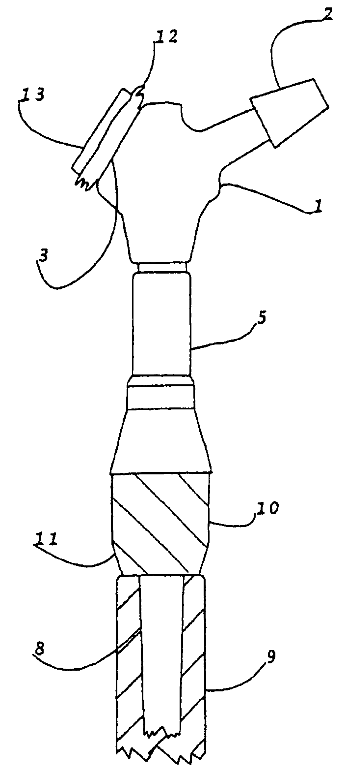
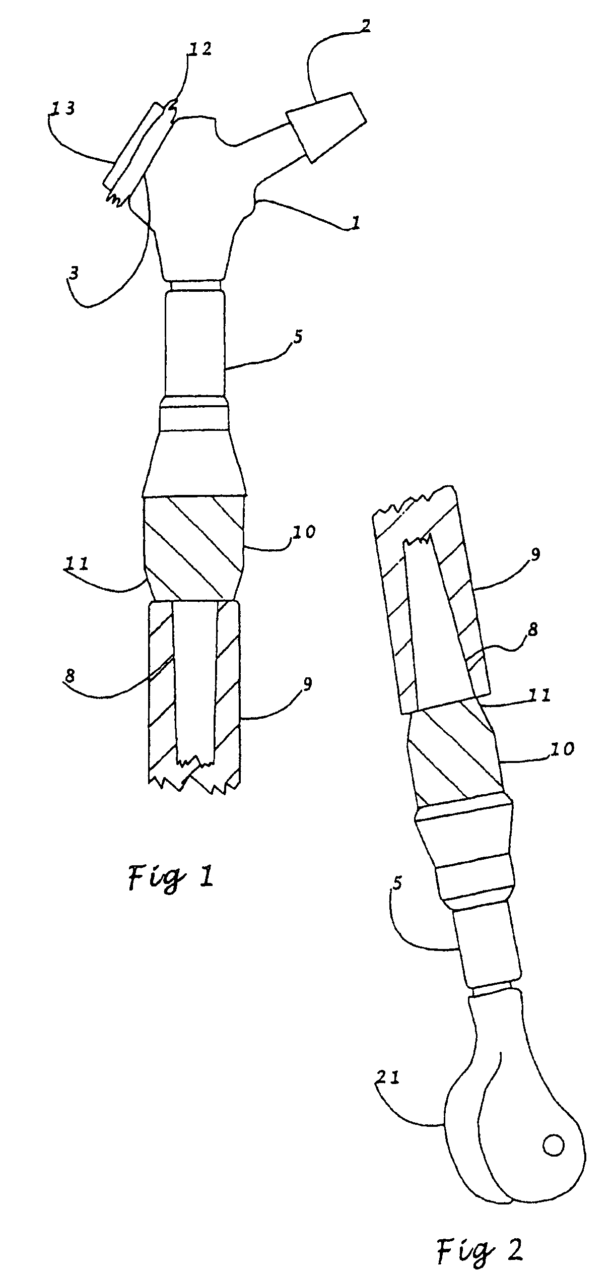
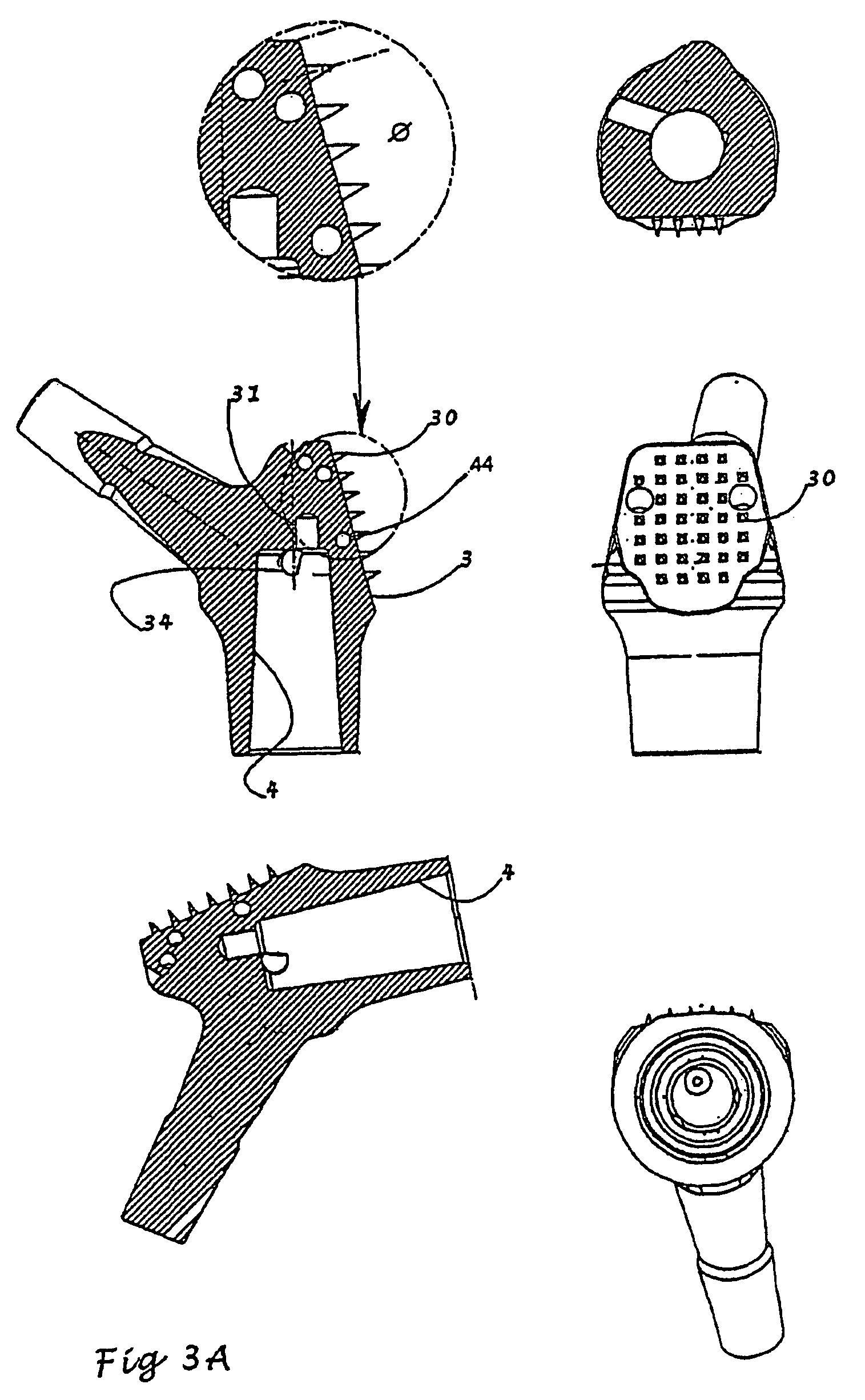
[0028]Referring firstly to FIG. 1, this drawing shows diagrammatically an assembled, proximal femoral prosthesis comprising a trochanter component 1 having a femoral neck 2, which is tapered to receive a femoral ball in a conventional fashion. The trochanter component is shown in more detail in the views shown in FIG. 3 and it may be seen that it corresponds roughly to the anatomical shape and has a generally flat face 3 for attachment to any residual bone or to soft tissues. The trochanter component 1 has an internal female taper, best seen in FIG. 3, and is assembled onto a male taper carried by a shaft 5. The detailed construction of shaft 5 are apparent from the views in FIG. 4 and it will be seen that shaft 5 has a male taper 33 at one end for engagement into the female taper of the trochanter component 1 and at its other end has a female taper 7 for engagement with one end of a stem 8 (shown in more detail in FIG. 5).

[0029]Stem 8 is fitted into a resected femur 9 either by pre...


PUM

PropertyMeasurementUnit
lengthsaaaaaaaaaa
diameteraaaaaaaaaa
external dimensionaaaaaaaaaa

Abstract

A prosthesis for partial replacement of a long bone in humans or animals, the prosthesis including: a proximal or distal end component forming one component of a prosthetic joint; a shaft on or assembled with the distal or proximal end component in use; a stem for engagement in a resected bone; and an initially separate collar assembled to the shaft or an extension thereof in use, the collar being dimensioned to abut the resected end face of the bone into which the prosthesis is to be fitted, wherein the end face of the collar facing the resected face of the bone is sized and shaped to correspond to the resected end face of the bone.

Description

CROSS-REFERENCE TO RELATED APPLICATION[0001]This application is a continuation-in-part of application Ser. No. 11 / 433,953 filed May 15, 2006, which is a continuation of application Ser. No. 10 / 450,559, filed Jun. 12, 2003, now U.S. Pat. No. 7,044,976.FIELD OF THE INVENTION[0002]This invention relates to prostheses for partial replacement of a long bone in human or animal bodies.BACKGROUND TO THE INVENTION[0003]In the case where limbs are badly damaged or large amounts of bone must be surgically removed, e.g. in the case of treatment of bone cancer, there is a need for prostheses which replace a large part of the natural bone and which can be assembled by the surgeon to meet a wide range of conditions. The present invention provides a modular system and components thereof for constructing effectively customised prostheses to meet a range of such surgical requirements. Typical requirements may be, for example, to replace the proximal or distal femur. Existing modular prostheses for th...

Claims


Application Information

Patent Timeline
Patent Type & Authority Applications(United States)
IPC IPC(8): A61F2/32A61F2/28A61B17/06A61B17/80A61F2/00A61F2/08A61F2/30A61F2/36A61F2/38A61F2/46
CPCA61B17/06166A61F2310/00796A61F2/0811A61F2/30734A61F2/30739A61F2/30767A61F2/30771A61F2/3607A61F2/367A61F2/3672A61F2/3676A61F2/3859A61F2002/2825A61F2002/2853A61F2002/30126A61F2002/30324A61F2002/30329A61F2002/30332A61F2002/30344A61F2002/30382A61F2002/30551A61F2002/30604A61F2002/30616A61F2002/307A61F2002/30708A61F2002/30738A61F2002/30772A61F2002/30785A61F2002/30808A61F2002/30813A61F2002/30818A61F2002/30822A61F2002/30827A61F2002/30843A61F2002/30892A61F2002/30894A61F2002/3611A61F2002/3625A61F2002/365A61F2002/4631A61F2002/4641A61F2220/0025A61F2220/0033A61F2230/0008A61F2250/0036A61F2250/0081A61F2250/0084A61F2310/00023A61F2310/00029A61F2310/00179A61B17/80A61F2002/30339A61F2002/3055A61F2002/30331A61F2/36
Inventor MESWANIA, JAY
Owner STANMORE IMPLANTS WORLDWIDE
Why Eureka
Try Eureka