Integrated Tire Pressure Diagnostic System and Method

a tire pressure diagnostic and integrated technology, applied in vehicle tyre testing, adaptive control, instruments, etc., can solve the problems of time-consuming and error-prone procedures, inability to identify situations in which all vehicle wheels are under-inflated, and inability to detect small changes in tire pressur

Inactive Publication Date: 2008-06-05
HUNTER ENG
View PDF27 Cites 38 Cited by
  • Summary
  • Abstract
  • Description
  • Claims
  • Application Information

AI Technical Summary

Benefits of technology

[0017]In an alternate embodiment, the vehicle service system is configured to provide instructions to an operator for moving the tires of a vehicle to alternate positions on the vehicle (i.e. a procedure commonly known as “rotating the tires”, such that the left rear tire is moved to the left front position, etc.) and to subsequently communicate the altered placement of the individual vehicle wheel assemblies to a TPMS system associated with the vehicle, enabling the TPMS system to provide proper identification of individual tire pressure measurements.

Problems solved by technology

However, indirect tire pressure monitoring systems cannot identify small changes in tire pressures, and are incapable of identifying situations in which all of the vehicle wheels are under-inflated.
Manual systems often require the operator to retrain or reposition the tire pressure sensors following a vehicle wheel rotation or service, a time-consuming and error-prone procedure.
Previous systems involved stand-alone hand-held tools or OEM scan tools and many manual tasks that could introduce errors or misinterpretations.
Previous procedures often included removing the wheels before the TPMS system is checked, leading to customer complaints that the service shop damaged the TPMS devices.
Previous hand-held systems do not typically check the ECU functionality in that system, but only the individual TPMS devices.
Current procedures are labor intensive, cumbersome, and error-prone due to the limitations mentioned above.

Method used


Image

  • Integrated Tire Pressure Diagnostic System and Method
  • Integrated Tire Pressure Diagnostic System and Method
  • Integrated Tire Pressure Diagnostic System and Method

Examples


Embodiment Construction

[0027]The following detailed description illustrates the invention by way of example and not by way of limitation. The description enables one skilled in the art to make and use the present disclosure, and describes several embodiments, adaptations, variations, alternatives, and uses of the present disclosure, including what is presently believed to be the best mode of carrying out the present disclosure.

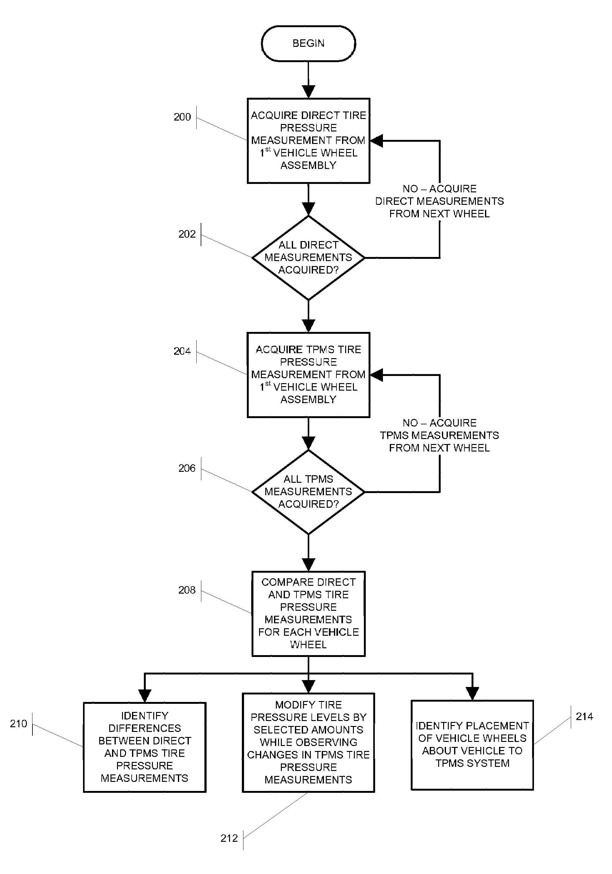
[0028]In a first embodiment, the present disclosure provides a computer-based vehicle service system 100, such as a wheel alignment system or a dedicated tire pressure analysis system, which is configured with a suitable or supplemental sensor 102 adapted to acquire direct measurements of the air pressure in one or more of the tires of a vehicle undergoing a service procedure. The sensor 102 may be of any conventional design intended to provide a signal representative of a measure of air pressure, and may be operatively coupled to a processor 104 of the vehicle service system 100 vi...


PUM


Abstract

A computer-based vehicle service system, such as a wheel alignment system, is configured to acquire and utilize measurements of the air pressure in the tires of a vehicle undergoing a service procedure.

Description

CROSS-REFERENCE TO RELATED APPLICATIONS[0001]The present application is related to, and claims priority from, U.S. Provisional Patent Application Ser. No. 60 / 867,938 filed on Nov. 30, 2006, and which is herein incorporated by reference.STATEMENT REGARDING FEDERALLY SPONSORED RESEARCH[0002]Not Applicable.BACKGROUND OF THE INVENTION[0003]The present invention is related to vehicle service systems, and in particular, to vehicle service systems such as vehicle wheel alignment systems, which are configured to acquire measurements of tire pressure for a wheel assembly of a vehicle undergoing a service procedure directly and from a tire pressure monitoring system sensor, and to utilize the acquired tire pressure measurements during a vehicle service procedure, such as to carry out diagnostic evaluation of the tire pressure monitoring system.[0004]Modern vehicle wheel assemblies on most motor vehicles today consist of a pneumatic tire mounted or seated on a wheel rim, such as shown in FIG. ...

Claims


Application Information

Patent Timeline
Patent Type & Authority Applications(United States)
IPC IPC(8): B60C23/04G01M17/02
CPCB60C23/0408B60C23/02G01B2210/26G01B21/26
Inventor COLARELLI, NICHOLAS J.STREGE, TIMOTHY A.
Owner HUNTER ENG
Why Eureka
Try Eureka