Device for overall machine tool monitoring

a technology for monitoring devices and machine tools, applied in process control, process control, instruments, etc., can solve problems such as unbalance in the attachment state of tools or detection of tool faults, and achieve the effects of simple configuration, simple learning, and simple position relation

Inactive Publication Date: 2008-06-05
MATSUSHITA ELECTRIC WORKS LTD
View PDF7 Cites 16 Cited by
  • Summary
  • Abstract
  • Description
  • Claims
  • Application Information

AI Technical Summary

Benefits of technology

[0011]In this configuration, a fault in the tool as well as tilt in an attachment position of the tool can be detected by using frequency components of the target signal as information on a state prior to machining operation. Further, since the frequency components of the envelop of the target signal are used as information during the machining operation, noise components such as accustic emissions generated during

Problems solved by technology

That is, unbalance in the attachment state of the tool or a fault

Method used


Image

  • Device for overall machine tool monitoring
  • Device for overall machine tool monitoring
  • Device for overall machine tool monitoring

Examples


Embodiment Construction

[0016]Embodiments of the present invention will now be described with reference to the accompanying drawings which form a part hereof.

[0017]A machine tool exemplified in an embodiment described below has a tool rotatably driven by a driving unit. There are various kinds of machine tools for machining such as cutting or polishing in the machine tool. Any driving source using a motor can serve as the driving unit, and a proper power transmission unit such as a gearbox or a belt can be provided between the driving source and the tool. Hereinafter, a spindle with a housing is exemplified as the driving unit.

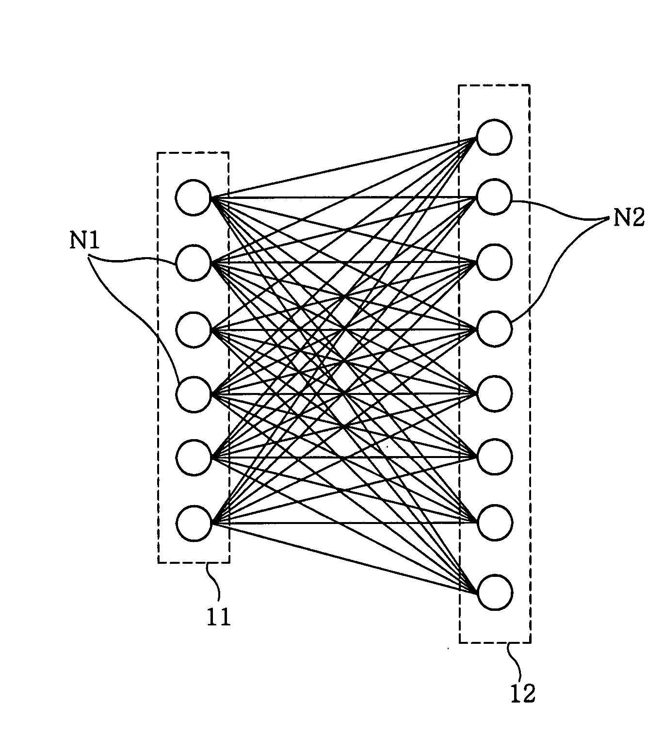
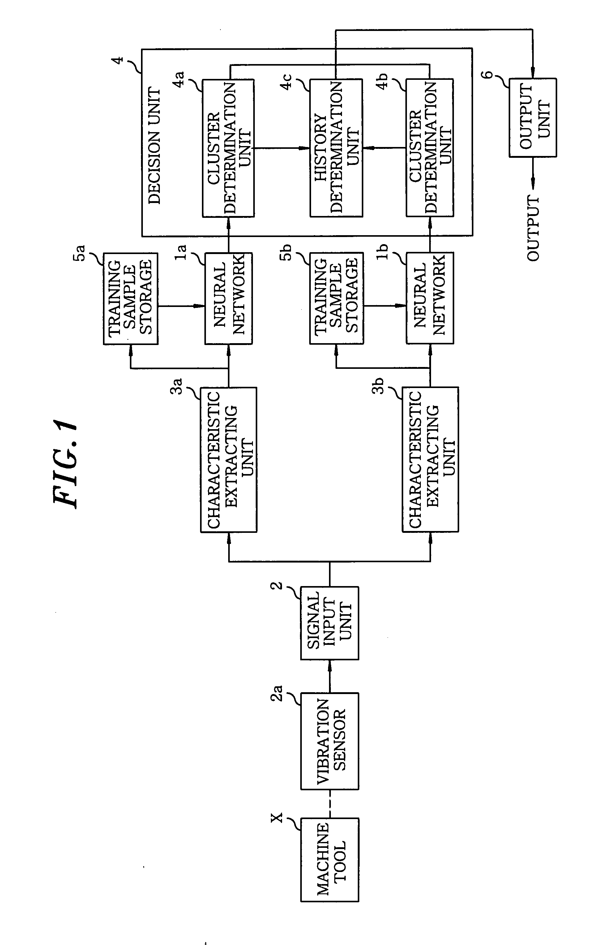
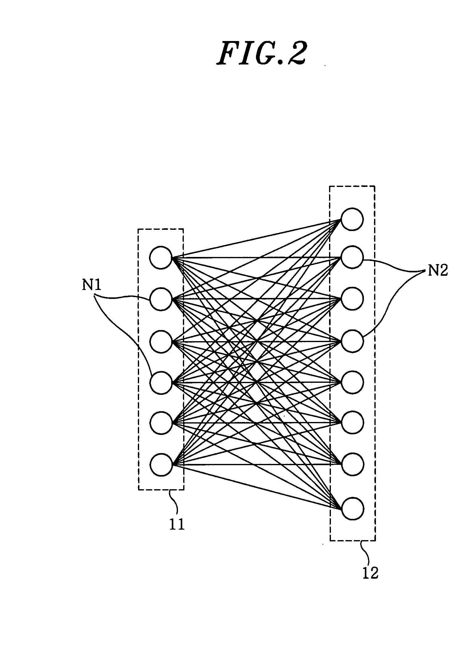
[0018]As shown in FIG. 1, a device for overall machine tool monitoring described in the present embodiment uses, e.g., unsupervised competitive learning neural networks 1a and 1b (hereinafter, simply referred to as neural networks if not otherwise necessary for some purpose). Supervised back propagation type neural networks can be also used as neural networks, but the unsupervised co...


PUM


Abstract

A first and a second neural network classify, into normal and abnormal categories, amounts of characteristics extracted from target signals generated when a machine tool is racing prior to machining a workpiece and while the machine tool is machining the workpiece, respectively. A determination unit determines whether an anomaly exists before the machine tool machines the workpiece and while the machine tool is machining the workpiece, and whether there is a fault in the machine tool, based on the classification results from the first and the second neural networks, deviation history between weight coefficients of neurons in an output layer included in the first neural network and the amounts of characteristics extracted by the first characteristics extracting unit, and deviation history between weight coefficients of neurons in an output layer included in the second neural network and the amounts of characteristics extracted by the second characteristics extracting unit.

Description

FIELD OF THE INVENTION[0001]The present invention relates to a device for overall machine tool monitoring and, more particularly, to a device for monitoring, prior to and during machining operation, an anomaly existence in the machine tool, and further for detecting a fault in the machine tool.BACKGROUND OF THE INVENTION[0002]Conventionally, there has been known that a technique for detecting vibrations generated while a machine tool is machining, so that monitoring chatter vibrations and unbalance of a grinding stone and the like while the machine tool is machining has been considered. In order to detect the vibrations, an acceleration or an accustic emission is monitored (see, e.g., Japanese Patent Laid-open Application No. H8-261818).[0003]Patent Reference discloses a technique for determining whether the chatter vibrations, unbalance of a grinding stone, or the like exist or not through monitoring a frequency spectrum. However, it is impossible for a person to monitor the freque...

Claims


Application Information

Patent Timeline
IPC IPC(8): G06F15/18
CPCG01H1/003G01H1/12G05B2219/37435G05B2219/33296G05B19/406
Inventor IKEDA, KAZUTAKA
Owner MATSUSHITA ELECTRIC WORKS LTD
Why Eureka
Try Eureka