Substrate processing apparatus and manufacturing method for semiconductor devices

a processing apparatus and semiconductor technology, applied in conveyors, packaging goods types, furniture, etc., can solve the problems of complex structure of batch cvd apparatus, inability to attach or remove the pod doors, etc., and achieve the effect of smooth transfer of storage containers

Active Publication Date: 2008-06-12
KOKUSA ELECTRIC CO LTD
View PDF10 Cites 24 Cited by
  • Summary
  • Abstract
  • Description
  • Claims
  • Application Information

AI Technical Summary

Benefits of technology

[0023]Installing an elevator mechanism in the above aspect allows the transfer device to transfer the storage container from the placement unit to inside the case over the opening and closing device so that besides smoot

Problems solved by technology

Pod doors are not attachable or removable in the batch CVD apparatus of the prior art, in the loading and unloading port for carrying the pod outside the apparatus into the batch CVD apparatus case or carrying the

Method used


Image

  • Substrate processing apparatus and manufacturing method for semiconductor devices
  • Substrate processing apparatus and manufacturing method for semiconductor devices
  • Substrate processing apparatus and manufacturing method for semiconductor devices

Examples


second embodiment

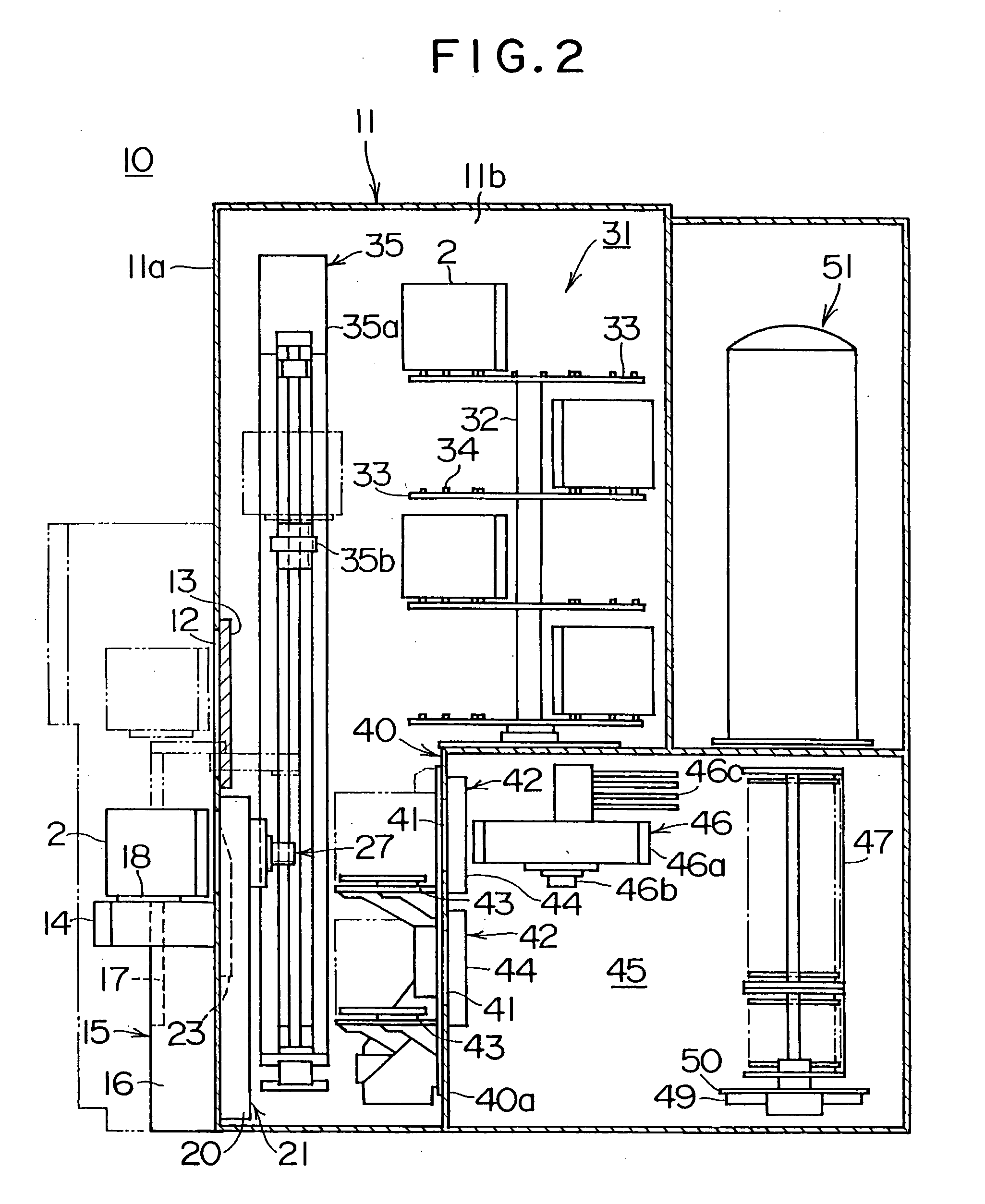
[0185]FIG. 7 is a side cross sectional view showing the batch CVD apparatus as the present invention.

[0186]The main point where this embodiment differs from the previous embodiment is only that a pod opener is installed only in the load port.

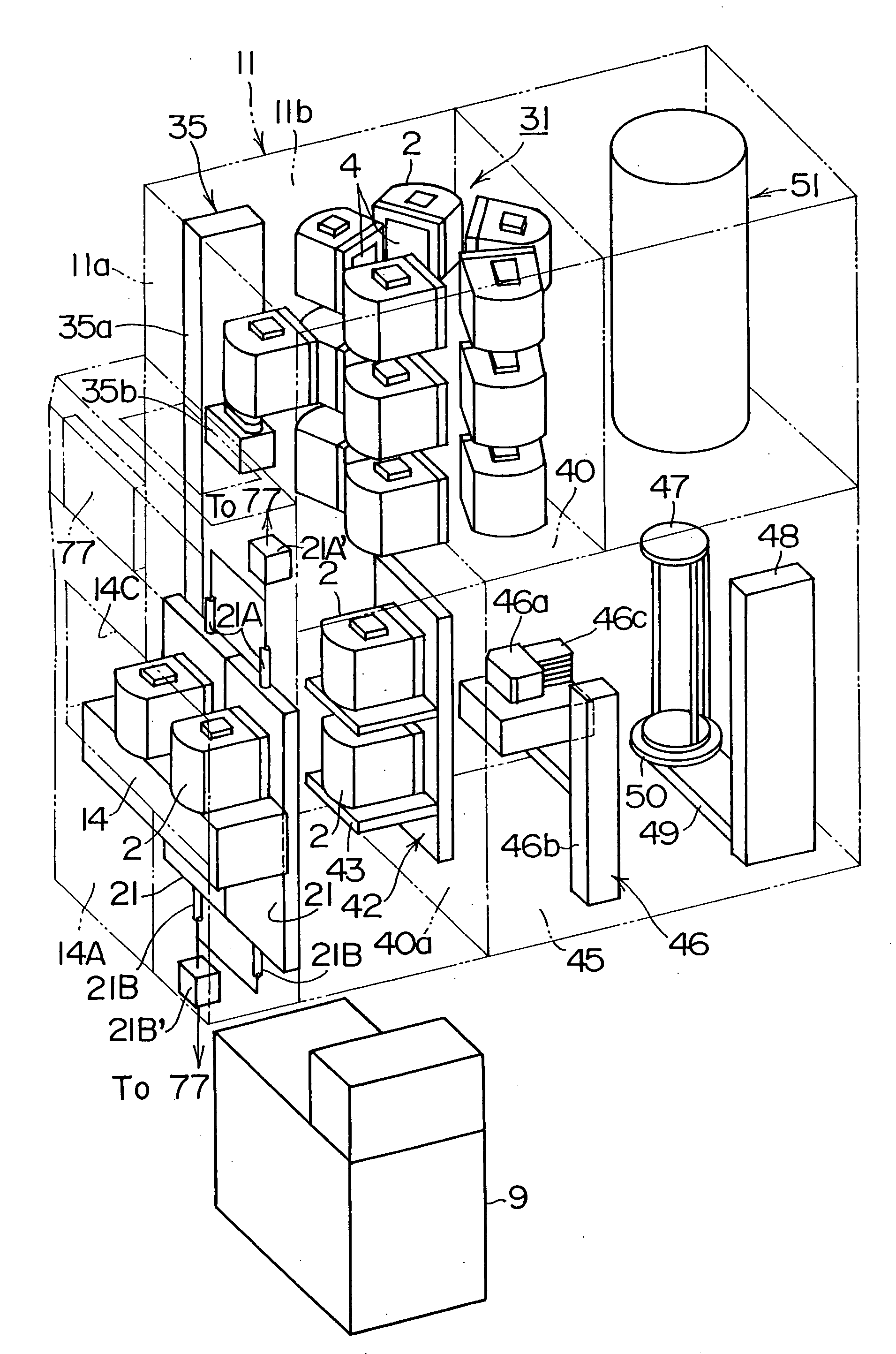
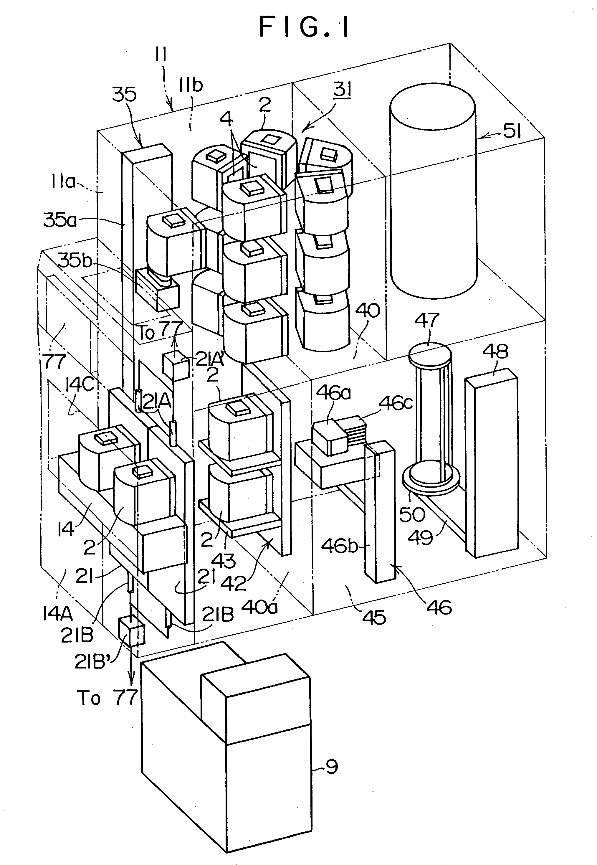
[0187]Namely as shown in FIG. 7, a load port 14 is installed in the front wall (divider wall) of the sub-case 40 forming the prechamber 45. A pod opener 83 is installed in this front wall 40a. A wafer loading and unloading opening 91 is formed in the rear wall 81a of a sealed case 81 forming a load lock chamber 80 of the pod opener 83. A door mechanism 92 for opening and closing this wafer loading and unloading opening 91 is also installed on the sealed case 81.

[0188]A wafer transfer mechanism 46 serving as the substrate transfer device is installed inside the prechamber 45. The wafer transfer mechanism 46 transfers the wafers 1 between the pod 2 and the boat 47 while the door mechanism 92 has opened the wafer loading and unloading opening 91.

[0...

first embodiment

[0192]A mapping device 84 is installed in the load lock chamber 80 the same as the pod opener 42 of the The mapping device 84 can move forward and rearward (perpendicularly) and upward and downward (parallel) to the door loading and unloading opening 82.

[0193]The effect of the pod opener in the above structure is described next.

[0194]The controller 77 controls the following operations.

[0195]As shown in FIG. 7, the pod 2 is mounted on the support stand 18 of the pod elevator 15, when the in-process transfer device carries the pod 2 into the load port 14 by way of the front opening 14C or the ceiling opening 14B.

[0196]The pod 2 is at that time positioned on the support stand 18 by the insertion of the kinematic pins 19 affixed to the support stand 18, into the positioning holes 5 on the lower surface of the pod 2.

[0197]Next, the pod 2 is moved towards the pod opener 83 in the load port 14, and the closure 86 of the pod opener 83 holds the door 4.

[0198]When the door 4 is held, the clo...

third embodiment

[0220]FIG. 8 is a side cross sectional view showing the batch CVD apparatus of the present invention.

[0221]This embodiment differs from the second embodiment in the point that the structure performs handling by gripping the upper section of the pod; and in the point that a pod stage mechanism capable of accepting the pod from a ceiling track overhead hoist transport (hereinafter called “OHT”) even while transferring the wafer within the pod is provided.

[0222]In other words, as shown in FIG. 8, a pod transfer device (hereinafter called “grip-type pod transfer device”) 100 for handling by gripping the upper section of the pod is installed along with the storage rack 31A in the storage chamber 11b adjoining the ceiling surface of the prechamber 45.

[0223]This grip-type pod transfer device 100 includes a pod elevator 101, and a pod transfer mechanism 102 raised and lowered by the pod elevator 101, and a grip unit 103 moved by the pod transfer mechanism 102. The grip unit 103 can extend o...


PUM

PropertyMeasurementUnit
Heightaaaaaaaaaa

Abstract

A substrate processing apparatus comprises a storage container for storing multiple substrates and whose substrate loading and unloading opening is shut by a lid, a loading and unloading port for carrying the storage container into and out of the case, a placement unit for placing the storage container in the loading and unloading port, a storage chamber provided adjacent to the loading and unloading port for storing the storage container, an opening and closing device for opening and closing the substrate loading and unloading opening of the storage container placed in the placement unit, a transfer device containing a holding mechanism for supporting the bottom of the storage container and transferring the storage container supported in the holding mechanism, over the opening and closing device between the inside and outside of the storage chamber, and an elevator mechanism for raising and lowering the placement unit between the placement unit height position where the opening and closing device opens and closes the storage container, and a height position where the transfer device gives and receives the storage container.

Description

BACKGROUND OF INVENTION[0001]1. Field of Invention The present invention relates to a substrate processing apparatus and a semiconductor device manufacturing method.[0002]The present invention for example is effective for use in a batch type vertical diffusion CVD apparatus for diffusing dopants or forming a thin film such insulating film, metallic film, or semiconductor film on semiconductor wafers (hereinafter called “wafers”) on which semiconductor integrated circuits (hereinafter called “IC”) are formed.[0003]2. Description of Related Art[0004]Batch type vertical diffusion CVD apparatus (hereinafter called “batch CVD apparatus”) are one type of substrate processing apparatus that is utilized in a state where holding multiple wafers in a storage container.[0005]The conventional storage container includes an open cassette, and a FOUP (front opening unified pod. hereinafter called “pod”). The open cassette is formed in a cubic parallelpiped box shape open on one pair of opposing si...

Claims


Application Information

Patent Timeline
IPC IPC(8): H01L21/67
CPCH01L21/67766H01L21/67769Y10T29/41H01L21/67775H01L21/67778H01L21/67772
Inventor ABURATANI, YUKINORI
Owner KOKUSA ELECTRIC CO LTD
Why Eureka
Try Eureka