Riding saddle and its method of manufacture

Inactive Publication Date: 2008-06-12
SELLERIE DE NONTRON
4 Cites 3 Cited by

AI-Extracted Technical Summary

Problems solved by technology

Nevertheless, their method of fabrication is sometimes difficult and lengthy, which can lead to cost that is not negligible.
Given the movements of the horse, that architecture necessarily leads to rough contacts and to significant impa...

Method used

[0064]Furthermore, a particularly useful and unexpected result is observed. The horizontal movement of the anterior portion of the tree causes pressure points on the horse's back to be distributed uniformly, thus greatly relieving the horse.
[0078]It should be observed that the head of each of...

Benefits of technology

[0014]An object of the present invention is to propose a riding saddle that makes it possible to...

Abstract

A riding saddle provided with a semi-rigid tree (1) is remarkable in that it includes a semi-rigid trapezium (2) facing the back (50) of the horse and on which the saddle is placed, which trapezium co-operates with the tree (1).

Application Domain

Engine sealsLeather manufacturing +2

Technology Topic

Engineering

Image

  • Riding saddle and its method of manufacture
  • Riding saddle and its method of manufacture

Examples

  • Experimental program(1)

Example

[0047]Elements present in more than one figure are given the same references in each of them.
MORE DETAILED DESCRIPTION
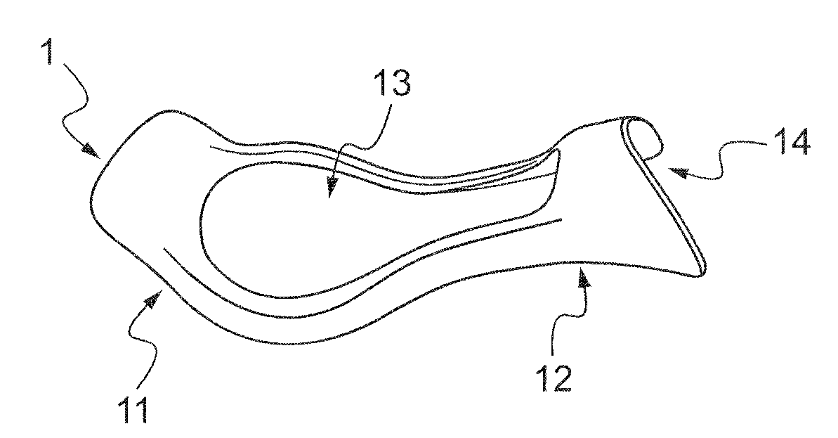
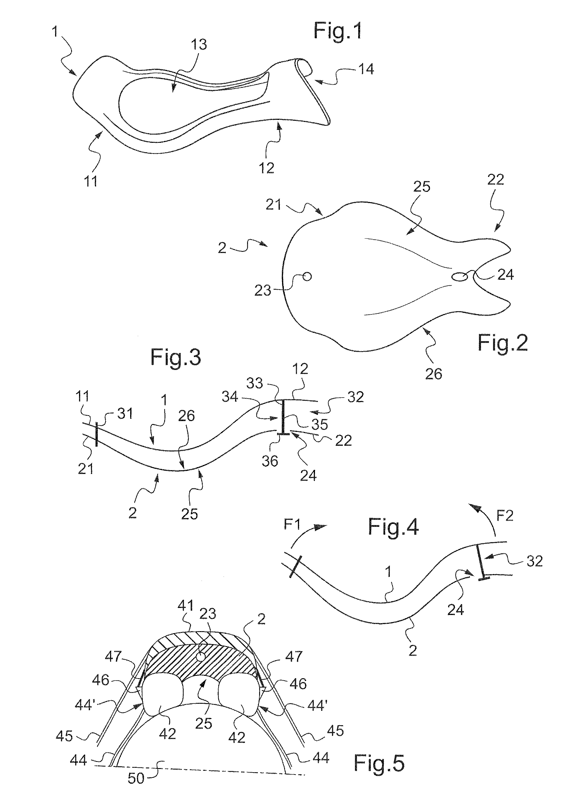
[0048]FIG. 1 is a diagrammatic view of a tree 1. The tree 1 is semi-rigid presenting a posterior portion 11, i.e. at the rear of the saddle, and thus remote from the horse's withers.
[0049]Furthermore, the tree is provided with an anterior portion 12, i.e. beside the horse's withers. It should also be observed that the tree possesses a rounded end 14 for allowing the horse's withers to move vertically.
[0050]Furthermore, there can be seen an opening 13 in the tree, the center of the tree being hollow. The opening 13 is then filled with straps on which the padding and covering of the saddle will rest.
[0051]It is explained below that other elements such as the flaps and the girth straps are also secured to the tree 1 so as to constitute a first assembly referred to for convenience, as a “seat”.
[0052]FIG. 2 is a diagrammatic view from beneath of a trapezium 2 of the invention. It can be seen that this trapezium is a semi-rigid plate and not just a piece of leather.
[0053]The trapezium 2 comprises a posterior portion 21 situated at the rear of the saddle and thus remote from the horse's withers. In addition, the trapezium 2 is provided with an anterior portion 22 beside the horse's withers.
[0054]Furthermore, the trapezium possesses a bottom face 25 facing the horse's back and a top 26 facing the tree 1.
[0055]Furthermore, in order to secure the tree 1 to the trapezium 2, the trapezium is provided with an orifice in the form of an oblong hose 24 in its anterior portion and with a round hole 23 in its posterior portion.
[0056]FIG. 3 is a diagrammatic section of a tree 1 arranged on a trapezium 2, the said tree 1 co-operating with the trapezium 2.
[0057]The posterior portion 11 of the tree 1 is secured to the posterior portion 21 of the trapezium 2 via engagement means 31, e.g. a screw that passes through the round hole 23 of the trapezium 2 to be screwed into an insert present in the tree 1. The top face 26 of the trapezium 2 then faces towards said tree 1. The engagement means 31 serve to secure the tree 1 to the trapezium 2 at their posterior portions 11, 21.
[0058]Similarly, the anterior portion 12 of the tree 1 is fastened to the anterior portion 22 of the trapezium 2 via a link 32.
[0059]By way of example, the link 32 is a pin having its first end 33 constituted by an insert secured to the tree 1. Its second end 34 is then a screw whose shank 35 projects from the trapezium 2, the screw head 36 facing the bottom face 25 of the trapezium 2.
[0060]The tree 1 then co-operates with the trapezium 2, and vice versa.
[0061]At rest, and with reference to FIG. 3, the tree 1 is spaced apart from the trapezium 2 in natural manner, given the way the posterior portions of the tree 1 and the trapezium 2 are fastened together via the engagement means.
[0062]In contrast, with reference to FIG. 4, when a rider sits on the saddle, the tree 1 is free to move at least in part relative to the trapezium 2, so the tree 1 is displaced and comes substantially to fit the shape of the trapezium 2. More precisely, the weight of the rider deforms the tree 1 and the trapezium 2 elastically. Their posterior and anterior portions are then displaced respectively along arrows F1 and F2. Furthermore, the tree 1 is movable relative to the trapezium 2, with the link 32 being displaced horizontally in the oblong hole 24.
[0063]The combination of these movements thus imparts a non-negligible damping power to the assembly comprising the tree 1 and the trapezium 2.
[0064]Furthermore, a particularly useful and unexpected result is observed. The horizontal movement of the anterior portion of the tree causes pressure points on the horse's back to be distributed uniformly, thus greatly relieving the horse.
[0065]The oblong shape of the oblong hole 24 in the trapezium 2 serves to avoid the shank 35 of the screw 34 coming into contact with the sides of the hole. The oblong hole thus serves both as a guide and also as a stroke limiter. In FIG. 4, it can be seen that the displacement of the tree is limited in the end by the pair comprising the oblong hole 24 and the link 32, with the link 32 coming into abutment against the oblong hole at the end of its travel.
[0066]It should be observed that using composite materials for fabricating the tree is particularly effective, insofar as such composite materials make it possible to obtain a tree that is semi-rigid, sufficiently rigid to constitute the reinforcement of the saddle, but also sufficiently flexible to be deformed without that breaking the tree. Advantageously, the same applies to the trapezium 2.
[0067]FIG. 5 is a diagrammatic hind view of a saddle placed on the back 50 of a horse, for the purpose of illustrating the method of the invention. The cantle of the saddle can be seen particularly clearly.
[0068]During a step a) of the method, the seat of the saddle is fabricated from a semi-rigid tree that is not visible in FIG. 5.
[0069]The hollow portion 13 of the tree 1 is initially filled with straps and then the tree 1 is covered in padding and a covering 41, e.g. made of leather.
[0070]Furthermore, using means that are not shown in the figures, two flaps 45 are installed on the sides of the tree to enable riders to grip the saddle. Similarly, it can be seen that the anterior portion of the tree is provided with two fixing tabs known as “points”47.
[0071]Finally, girth straps (not shown) are fastened to the tree for the purpose of attaching the girth for holding the saddle on the horse, with the girth then going round the body of the horse.
[0072]In addition, the tree is also fitted with stirrup bars (not shown) for securing the stirrup leathers to the saddle.
[0073]At the end of this step a), all of the component elements of the seat have thus been assembled.
[0074]During step b), optionally performed simultaneously with step a), the frame of the seat is fabricated.
[0075]The frame is provided with a semi-rigid trapezium 2 with each of its sides including a respective panel 42.
[0076]These panels 42 are stuffed with padding and they are arranged on the back 50 of the horse.
[0077]In addition, the panels 42 are reinforced with rigid reinforcement of composite materials, with threaded inserts (not shown) being arranged in the reinforcements. Thus, each panel is fastened to the trapezium 2 via at least one screw passing through the trapezium and being received in an insert in the panel.
[0078]It should be observed that the head of each of these screws is disposed on the top face 26 of the trapezium, i.e. the face of the trapezium that faces the tree and not the back of the horse. This feature is important since it makes it possible to eliminate pressure points on the back 50 of the horse, thereby improving the horse's comfort.
[0079]Furthermore, a sweat flap 44 is fastened on each panel 42. Similarly, each panel 42 includes a pocket 46, on an outside face 44′, i.e. a face of the panel that does not face towards a flank of the horse.
[0080]Step b) is then complete.
[0081]Consequently, during a step c), following steps a) and b), the saddle is completed by fastening the seat to the frame.
[0082]During a preliminary stage of step c, the fixing tabs 47 of the seat are inserted into the pockets 46 of the sweat flap 44. This serves in particular to position the seat properly relative to the frame.
[0083]Thereafter, during a final stage of step c), the posterior portion of the tree is fastened to the posterior portion of the trapezium 2 using the engagement means 31. The engagement means 31 are constituted by a screw, for example, passing through the round hole 23 in the trapezium 2, and screwed into an insert that is secured to the tree.
[0084]In addition, the anterior portion 12 of the tree 1 is connected to the anterior portion 22 of the trapezium 2 via a link 32. More precisely, the link 32 is constituted for example by an insert 33 secured to the tree 1 and by a screw 34. The screw then passes through an oblong hole 24 in the trapezium 2 so as to be screwed into the insert 33 of the tree 1, with a portion of the screw, including its head 36, thus projecting from the trapezium 2 out from the saddle.
[0085]Naturally, the present invention can be subjected to numerous variants as to its implementation. Although several variants are described above, it will readily be understood that it is not conceivable to identify exhaustively all possible variants. It is naturally possible to envisage replacing any of the means described by equivalent means without going beyond the ambit of the present invention.

PUM

no PUM

Description & Claims & Application Information

We can also present the details of the Description, Claims and Application information to help users get a comprehensive understanding of the technical details of the patent, such as background art, summary of invention, brief description of drawings, description of embodiments, and other original content. On the other hand, users can also determine the specific scope of protection of the technology through the list of claims; as well as understand the changes in the life cycle of the technology with the presentation of the patent timeline. Login to view more.
Why Eureka
Try Eureka