Bowstring Cam for Compound Bow

a bow and compound bow technology, applied in bows/crossbows, white arms/cold weapons, weapons, etc., can solve the problems of waste of power limb energy, difficulty in achieving goals, and bowstring not optimally accelerating arrows, so as to improve the overall behavior of compound bows, accelerate bowstring and arrow, and equal flexing of upper and lower power limbs

Inactive Publication Date: 2008-06-12
BOICE RICHARD K MR
View PDF8 Cites 34 Cited by
  • Summary
  • Abstract
  • Description
  • Claims
  • Application Information

AI Technical Summary

Benefits of technology

[0009]It is still another object to improve overall behavior of the compound bow.
[0010]One aspect of this invention involves an improvement to compound bows of the type that include a riser having an upper end and a lower end, with upper and lower resilient power limbs, i.e., spring limbs, that have their inboard ends affixed to the upper and lower ends of the riser, and synchronizing means, e.g., a cam and cable arrangement, for ensuring equal flexing of the upper and lower power limbs upon draw and release of the bowstring. In the bow that employs the bowstring cam(s) according to preferred embodiments of the invention, upper and lower bowstring cams each are rotatably held at their axes on outboard ends of the upper and lower power limbs, and there are also associated upper and lower power cam arrangements, each having one or more inboard cams rotatably held at a rigid portion of the riser, one or more outboard power cams affixed onto the associated bowstring cam to rotate with it, and one or more flexible inextensible cam cables extending over the periphery of the associated inboard and outboard power cams. The power cam arrangement is configured so as to cooperate and thus to determine draw characteristics of the bow. In embodiments of this invention, the bowstring cams are provided with a cam profile with a lobe or apex oriented such that the radius, from the axis thereof to the tangent with the bowstring, diminishes as the bowstring is drawn and increases as the bowstring returns after release from a drawn position to the full brace position. This changes the mechanical advantage of the cams on the bowstring after the bowstring is released so as to accelerate the bowstring and arrow. In other words, the rotational energy of the bowstring cam is transferred more efficiently to the arrow.
[0011]In some preferred arrangements, the bowstring cams may be forged of a lightweight metal. The bowstring cams may rotate over an angle exceeding 90 degrees between fully drawn and fully returned positions. The offset ratio of the bowstring cam, i.e., the size of the base circle relative to the lobe of the cam, may be on the order of ⅔, and in one preferred embodiment about 0.633. The profile of the bowstring cam achieves an optimal acceleration of the bow string and arrow, so that more of the bow's energy is transferred as kinetic energy to the arrow. This also gives the bow a quieter action.
[0012]In the present improvement to the bowstring cam, which may be at the upper limb, lower limb, or both limbs of the bow, the bowstring cam is provided with an acircular profile, and there is a second power cam on one side or on both sides of the bowstring cam. The second power cam is offset to one side of the bowstring axis, such that at the end of travel (such as when the bowstring is fully released) the power cables are pulling in a common direction to rotate the bowstring cam. This configuration results in improved acceleration of the arrow throughout the travel of the bowstring.

Problems solved by technology

These goals have been difficult to achieve.
This means that the bowstring does not accelerate the arrow optimally, and at least some of the energy stored in the power limb is wasted.
Also, any energy that remains in the bow will cause bow noise.
That is, the inefficient design of the prior compound bows will cause the bowstring to snap when the arrow is released.
Previous proposals for compound bows involving bowstring cams have not configured the mechanical advantage of the cam relative to the bowstring to maximize the energy transfer to the arrow.

Method used


Image

  • Bowstring Cam for Compound Bow
  • Bowstring Cam for Compound Bow
  • Bowstring Cam for Compound Bow

Examples


Embodiment Construction

[0022]The compound bow on which the improved bowstring cam may be employed is described in my earlier U.S. Pat. No. 6,776,148, and that bow is described briefly here, but the contents of that patent are incorporated here by reference.

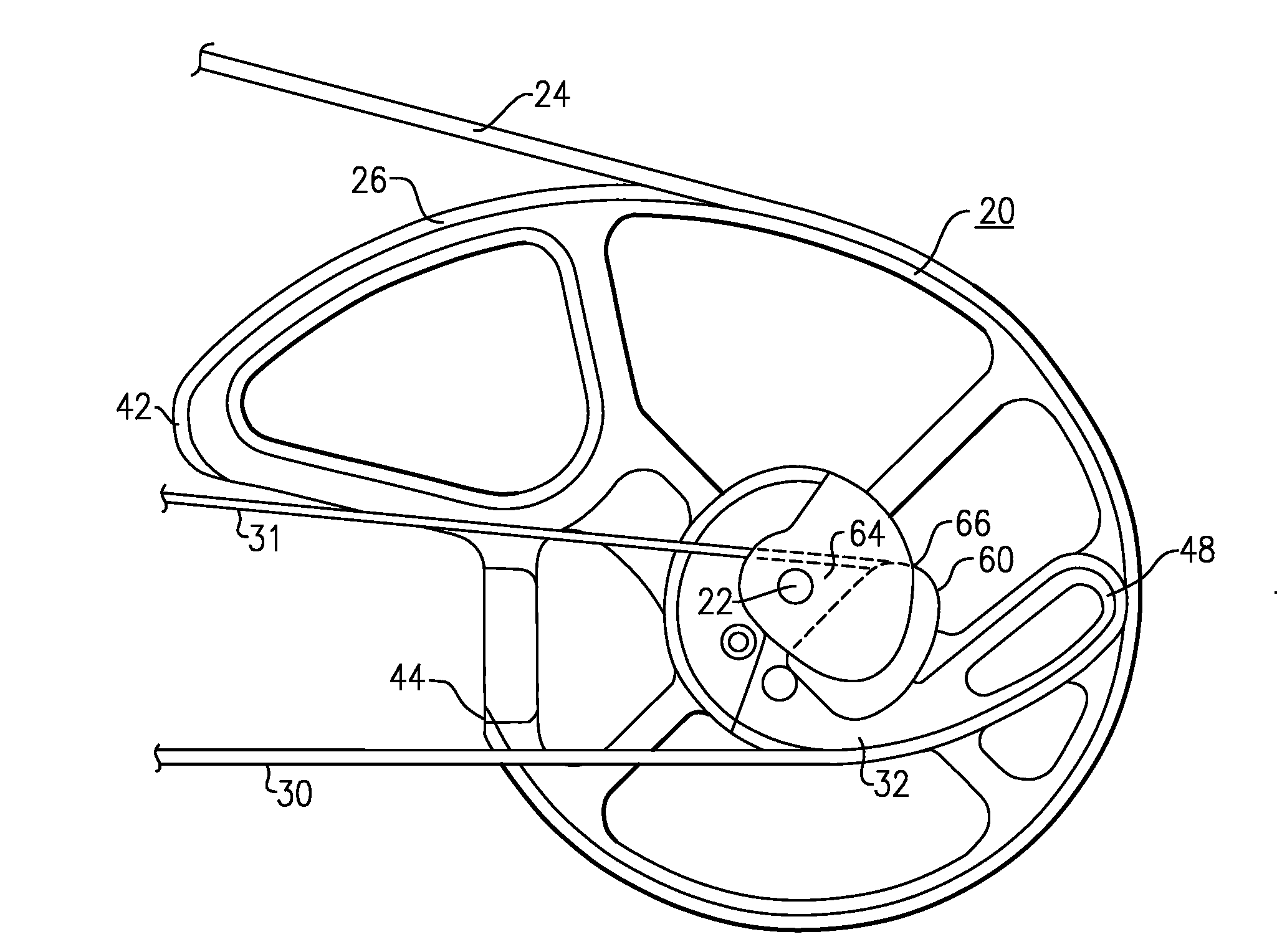
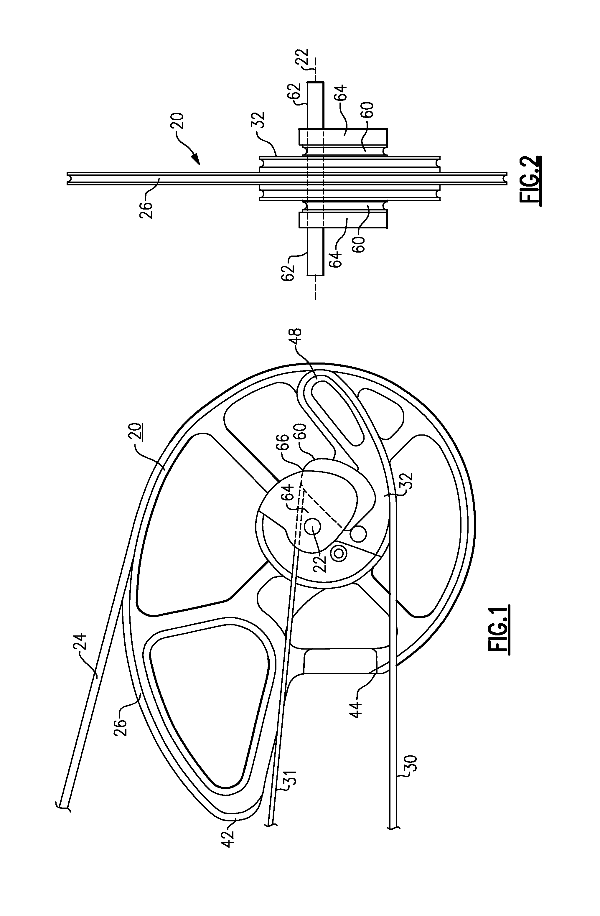
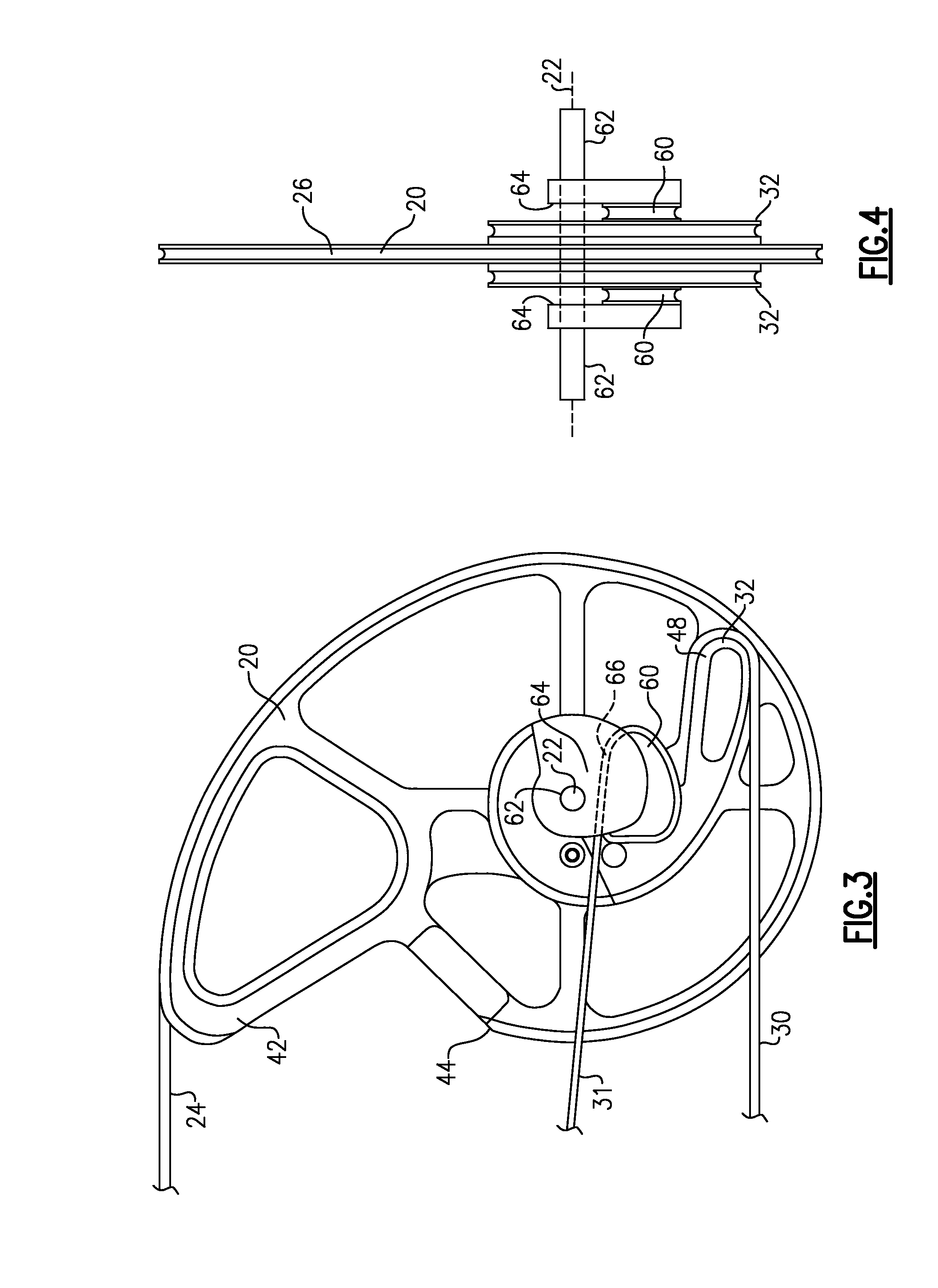
[0023]The compound bow has a riser or handle portion at its center with upper and lower power limbs or spring limb portions with inboard ends that are affixed onto at the upper and lower ends of the riser. The bow is considered in its normal, upright shooting orientation, as is conventional. There are upper and lower bowstring cam assemblies, e.g., bowstring cam 20, that are pivotally or rotationally attached at respective pivot axes to the outboard ends of the power limb members. A bow string 24 is attached to each bowstring cam 20 and rides in a peripheral groove or channel 26 in each of these cams, which groove is adapted to receive the bow string 24. Synchronizing pulleys are pivotally mounted on the riser near the ends. A continuous synchronizing c...


PUM


Abstract

A bowstring cam assembly for compound archery bow has a bowstring cam member that is journaled at an end of the bow power limb. First and second power cams are affixed onto the bowstring cam member to rotate with it, and first and second flexible inextensible cam cables extend over the periphery of the associated power cams. The cam cables and the power cams cooperate to determine draw characteristics for the bow. The bowstring cam member is provided with an acircular cam profile. The second power cam is situated to one side of the axis of the bowstring cam, such that at an end of travel, i.e., at full release, both the first and second power cables are pulling in a common direction.

Description

[0001]This application claims priority under 35 U.S.C. § 119(e) of Provisional Patent Application Ser. No. 60 / 873,238, filed Dec. 7, 2006.BACKGROUND OF THE INVENTION[0002]This invention is directed to the field of archery, and more specifically to compound bows of the type employing cams and control cables to achieve a programmed draw weight, and the latter being variable with draw length. The invention is more particularly concerned with improvements to such compound bows which make the bows more compact and streamlined, and which permit the archer to select the bow's draw characteristic, and which increases the bow's shooting performance.[0003]This invention is more particularly directed to compound bows of the type that are described in my earlier U.S. Pat. No. 6,776,148 (Aug. 17, 2004). That patent is incorporated herein by reference. The invention is directed to an improvement to the bowstring cam member of the type disclosed therein. The bowstring cam members are supported on ...

Claims


Application Information

Patent Timeline
Patent Type & Authority Applications(United States)
IPC IPC(8): F41B5/14
CPCF41B5/105F41B5/10
Inventor ISLAS, JOHN J.
Owner BOICE RICHARD K MR
Why Eureka
Try Eureka