Spatial localization of light-generating portions in LEDs

a technology of leds and light-generating parts, applied in the field of light-emitting diodes, can solve the problems of poor light extraction and inefficient light collimation

Active Publication Date: 2008-06-12
LUMINUS DEVICES
View PDF77 Cites 54 Cited by
  • Summary
  • Abstract
  • Description
  • Claims
  • Application Information

AI Technical Summary

Problems solved by technology

In some light-emitting devices, significant absorption of light within a light-generating portion can lead to poor light extraction and / or inefficient collimation of light.

Method used


Image

  • Spatial localization of light-generating portions in LEDs
  • Spatial localization of light-generating portions in LEDs
  • Spatial localization of light-generating portions in LEDs

Examples


Embodiment Construction

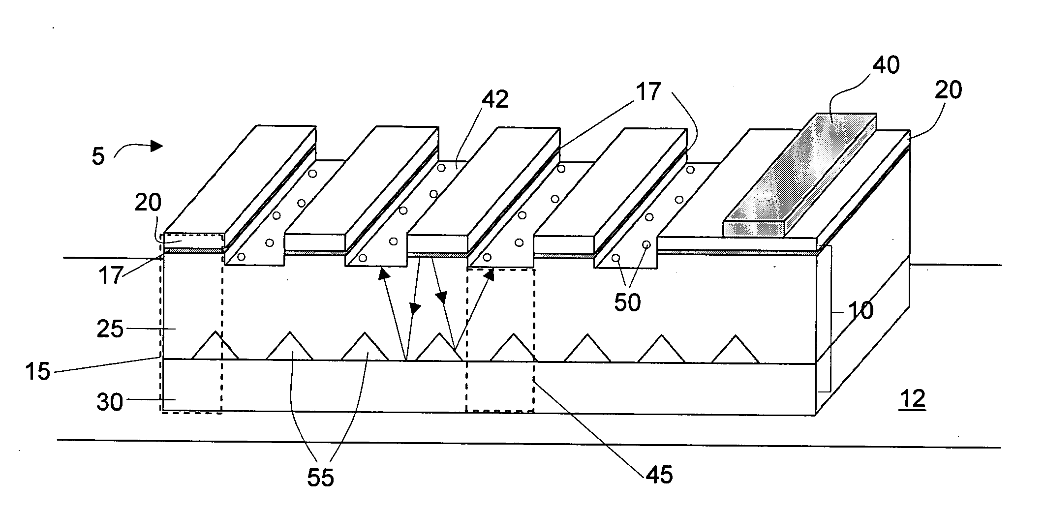
[0027]Light-emitting devices (e.g., LEDs) and methods associated with such devices are provided. As shown schematically in FIG. 1, an LED may include a light-generating portion 1 (which includes an active region) that is spatially isolated from a light-extraction portion 3. This separation of light-generating portion(s) from light-extraction portion(s) can allow light generated by the device to propagate and pass through regions of low absorption (e.g., light-extraction portions) rather than in regions of high absorption (e.g., light-generating portions). The low absorption regions allow photons to have longer lifetimes and inherently increase the escape probability of the photons, which in turn, can enhance light emission. In some embodiments, the device includes a distribution of light-generating portions that are spatially localized and separated (e.g., horizontally or vertically) from one or more patterned light extraction portions. Accordingly, the device may include a light ex...


PUM


Abstract

Light-emitting devices (e.g., LEDs) and methods associated with such devices are provided. In some embodiments, the device includes a distribution of light-generating portions (including active regions) that are spatially localized and separated (e.g., horizontally or vertically) from one or more patterned light extraction portions. This arrangement can allow light generated by the device to propagate and pass through regions of low absorption (e.g., light-extraction portions) rather than in regions of high absorption (e.g., light-generating portions), which can enhance light emission. In some instances, the devices include one or more series of light extraction portions with features arranged in a first and / or second pattern, which may be formed on one or more interfaces of the device (e.g., an emission surface). Patterns can be defined by a series of features (e.g., holes) having certain characteristics (e.g., feature size, depth, nearest neighbor distances) which may be controlled to influence properties of the light emitted from the device, including improving extraction and / or collimation of the emitted light.

Description

FIELD OF INVENTION[0001]The present embodiments relate generally to light-emitting devices, and more particularly to light-emitting diodes (LEDs), and specifically, to LEDs that have light-generating portions that are spatially isolated from light-extraction portions.BACKGROUND[0002]A light-emitting diode (LED) can often provide light in a more efficient manner than an incandescent light source and / or a fluorescent light source. The relatively high power efficiency associated with LEDs has created an interest in using LEDs to displace conventional light sources in a variety of lighting applications. For example, in some instances LEDs are being used as traffic lights and to illuminate cell phone keypads and displays. Many technological advances have led to the development of high power LEDs by increasing the amount of light emission from such devices.[0003]Typically, an LED is formed of multiple layers, with at least some of the layers being formed of different materials. In general...

Claims


Application Information

Patent Timeline
Patent Type & Authority Applications(United States)
IPC IPC(8): H01L33/00H01L33/08H01L33/10H01L33/22H01L33/40
CPCH01L33/08H01L33/405H01L33/22H01L33/10
Inventor POKROVSKIY, ALEXANDER L.LIM, MICHAELNEMCHUK, NIKOLAY I.ERCHAK, ALEXEI A.MINSKY, MILAN SINGH
Owner LUMINUS DEVICES
Why Eureka
Try Eureka