Light absorbing coating with high absorption capacity

a technology of light absorbing coating and absorption capacity, which is applied in the direction of cathode-ray/electron beam tube vessel/container, cathode-ray/electron beam tube/container, auxillary/base layers of photosensitive materials, etc., and can solve the problem of limited performan

Inactive Publication Date: 2002-01-01
COMMISSARIAT A LENERGIE ATOMIQUE ET AUX ENERGIES ALTERNATIVES
View PDF8 Cites 40 Cited by
  • Summary
  • Abstract
  • Description
  • Claims
  • Application Information

AI Technical Summary

Benefits of technology

The function of this optically continuous metal layer formed on the substrate is to prevent light transmission and to reflect light towards the absorbent layer(s).
Another advantage resulting from the low thickness of a coating according to the invention is the limitation of surface diffusion that is typically less than 1% in the visible range.

Problems solved by technology

The performance is then limited due to mechanical strength problems.

Method used


Image

  • Light absorbing coating with high absorption capacity
  • Light absorbing coating with high absorption capacity
  • Light absorbing coating with high absorption capacity

Examples


Embodiment Construction

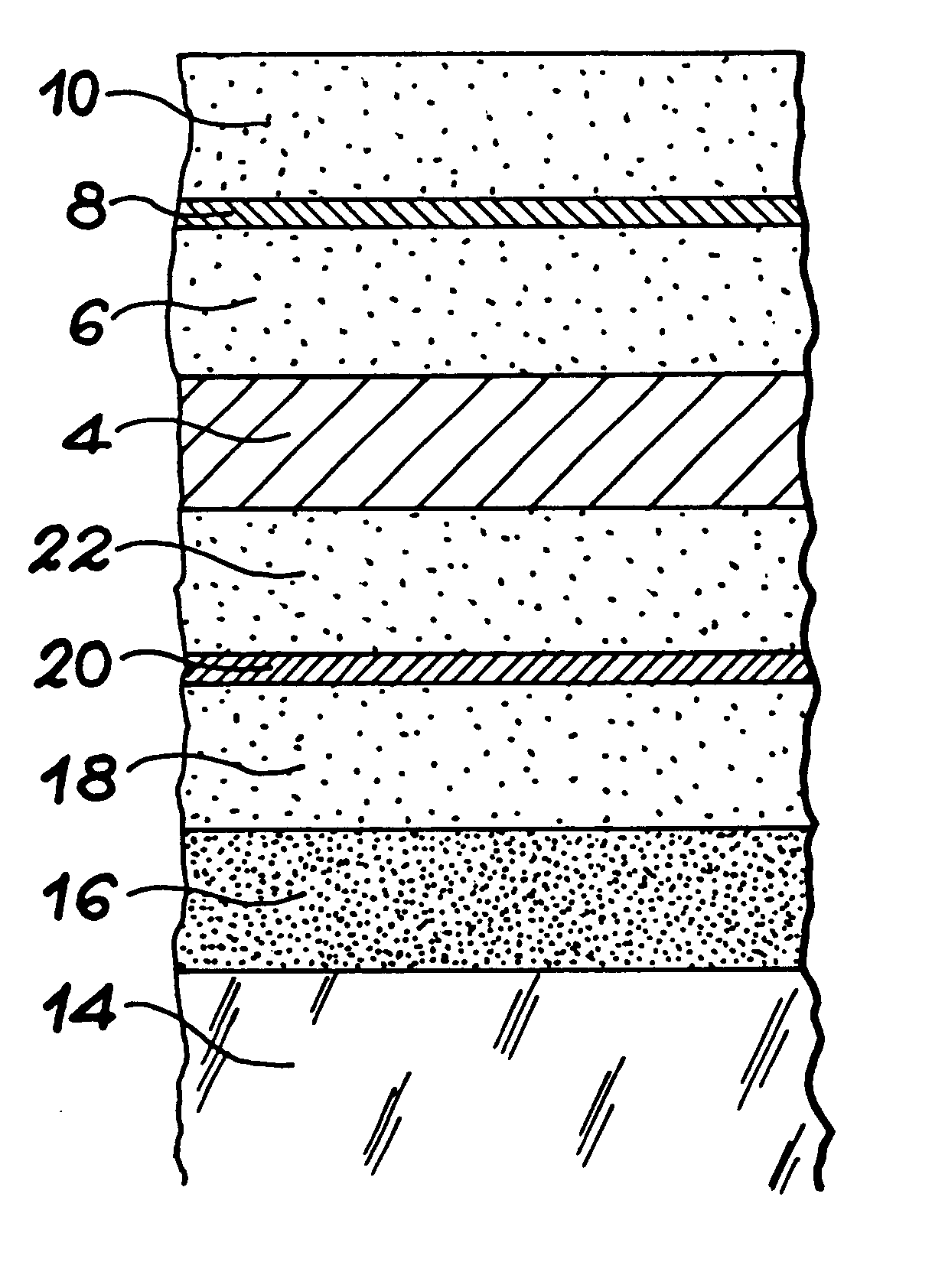
The purpose of this invention is to design a multilayer coating with a high absorption capacity (absorption of more than 95% of light) in the visible near infrared range, while minimizing risks of mechanical instability related to stresses in the layers in this absorbent coating.

The invention achieves this using an absorbent multi-layer structure that includes at least one thin metal layer as an absorption element, with the specific feature that it is optically discontinuous.

In particular, as we will see in the examples given later, this restricts the total thickness of the absorber to less than 200 nm, while providing absorption of between 97% and 99% within the visible-near infrared range.

Specifically, the purpose of the invention is a light absorbing coating in a given spectral range within the visible-near infrared range, this coating being formed on a substrate and characterized in that it comprises:

at least one layer of thin metal which is absorbent in this determined spectral...


PUM

PropertyMeasurementUnit
thicknessaaaaaaaaaa
thicknessaaaaaaaaaa
thicknessaaaaaaaaaa

Abstract

Light absorbing coating with high absorption capacity.This coating comprises at least one thin optically discontinuous metal layer (8), absorbent within a determined spectral range in the visible-near infrared range, and at least one dielectric layer (10) transparent within this range and formed on the thin layer. Application to imagery.

Description

This invention relates to a light absorbing coating.It is a thin multi-layer coating, with an absorption function in the visible and / or near infrared spectral range.The invention is particularly applicable to imagery, to limit parasite reflections and improve the separation between different detection channels, display screens and optical disks in which the function of the coating is to improve the contrast.The invention is particularly applicable to:optical systems designed for space applications,high precision imagery (telemetry),flat liquid crystal display or microtip display, andhigh definition television.STATE OF PRIOR ARTOne known method of making an absorbent coating (in the visible-near infrared range) consists of trapping a maximum amount of light that penetrates into the coating, and if possible to limit the amount of reflected light.In most cases, parasite reflections are restricted by depositing an anti-reflection layer (AR) with a wide spectral range, on an absorbent la...

Claims


Application Information

Patent Timeline
Patent Type & Authority Patents(United States)
IPC IPC(8): G02F1/1335G02B5/22G02F1/13H01J29/89G11B7/135G02B5/00G02B5/28
CPCG02B5/22H01J29/896G02F1/133512G11B7/135
Inventor QUESNEL, ETIENNECHATON, PATRICK
Owner COMMISSARIAT A LENERGIE ATOMIQUE ET AUX ENERGIES ALTERNATIVES
Why Eureka
Try Eureka