RFID sensor tag antenna using coupling feeding method

a technology of rfid sensor tag and feeding method, which is applied in the direction of resonant antenna, substantially flat resonant element, instruments, etc., can solve the problems of limiting the use of sensor tags, and achieve the effect of reducing reducing the width and length of the slot, and increasing the resistance component of the input impedan

Inactive Publication Date: 2008-06-12
ELECTRONICS & TELECOMM RES INST
View PDF9 Cites 25 Cited by
  • Summary
  • Abstract
  • Description
  • Claims
  • Application Information

AI Technical Summary

Benefits of technology

[0031]A resistance component of the input impedance is reduced by reducing a width and a length of the slot, and

Problems solved by technology

As a result, an antenna type may be changed according to an application to which a sensor tag is attached, which may be a factor limiting

Method used


Image

  • RFID sensor tag antenna using coupling feeding method
  • RFID sensor tag antenna using coupling feeding method
  • RFID sensor tag antenna using coupling feeding method

Examples


Embodiment Construction

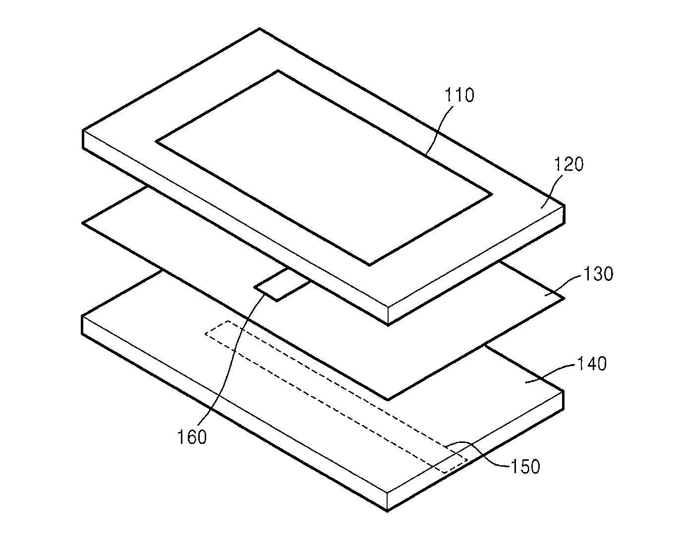
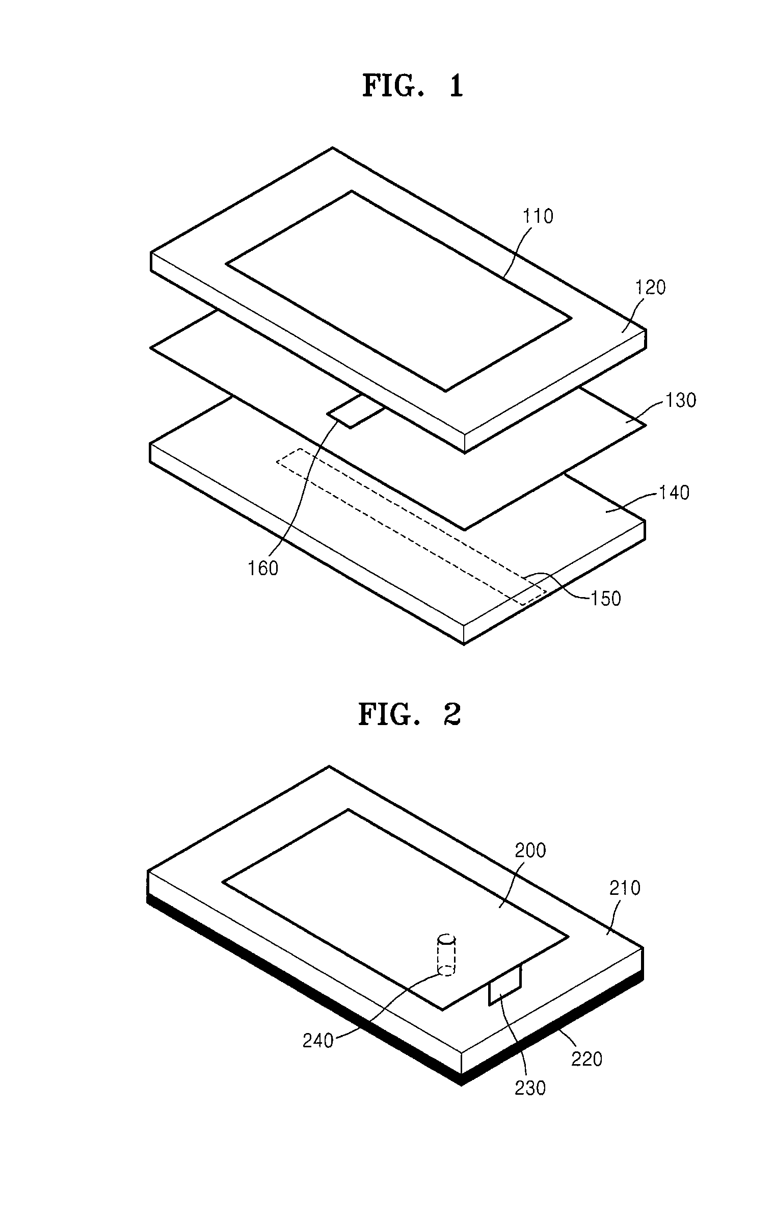
[0041]The present invention will now be described more fully with reference to the accompanying drawings, in which exemplary embodiments of the invention are shown. FIG. 1 is an exploded perspective view illustrating the structure of a conventional micro-strip patch antenna using an aperture coupling feeding method. Referring to FIG. 1, the conventional micro-strip patch antenna includes a radiation patch 110 for electromagnetic wave radiation, a first dielectric layer 120, a ground layer 130, a second dielectric layer 140 for micro-strip feeding, a micro-strip line 150 for antenna feeding, and a slot 160 for electromagnetic wave coupling.

[0042]The radiation patch 110 for electromagnetic wave radiation is disposed on the first dielectric layer 120, and the ground layer 130 is disposed on a bottom surface of the first dielectric layer 120.

[0043]The slot 160 for electromagnetic wave coupling is formed in the ground layer 130, and the second dielectric layer 140 for micro-strip feeding...


PUM


Abstract

Provided is a radio frequency identification (RFID) sensor tag antenna using an aperture coupling feeding method, including: a radiation patch for determining a resonance frequency of the RFID sensor tag antenna, which is disposed in an uppermost portion of the RFID sensor tag antenna; a first dielectric layer disposed on a bottom surface of the radiation patch and interposed between the radiation patch and a ground layer disposed to be parallel with the radiation patch; and a slot formed in a side of the ground layer and coupling RF signals to the RFID sensor tag antenna. Thus, the RFID sensor tag antenna can separately adjust resistance and reactance components of input impedance. As a result, the RFID sensor tag antenna can be matched with an RFID sensor tag board without an additional matching circuit.

Description

CROSS-REFERENCE TO RELATED PATENT APPLICATION[0001]This application claims the benefit of Korean Patent Application No. 10-2006-0125036, filed on Dec. 8, 2006, in the Korean Intellectual Property Office, the disclosure of which is incorporated herein in its entirety by reference.BACKGROUND OF THE INVENTION[0002]1. Field of the Invention[0003]The present invention relates to a radio frequency identification (RFID) sensor tag antenna using an aperture coupling feeding method, and more particularly, to a platform-insensitive sensor tag antenna having an aperture coupling feeding structure and capable of uniformly maintaining characteristics of sensor tags regardless of variations in a material to which the sensor tags are attached.[0004]This work was supported by the IT R&D program of MIC / IITA [2005-S-106-02, Development of Sensor Tag and Sensor Node Technologies for RFID / USN][0005]2. Description of the Related Art[0006]Radio frequency identification (RFID) sensor tags are semi-passive...

Claims


Application Information

Patent Timeline
IPC IPC(8): H04B7/00
CPCG06K19/07749H01Q9/0407H01Q9/0485H01Q1/2225H01Q1/38H01Q13/085
Inventor CHOI, WON KYUSON, HAE WONJUNG, JAE-YOUNGYEO, JUNHOCHOI, GIL YOUNGPYO, CHEOL SIG
Owner ELECTRONICS & TELECOMM RES INST
Why Eureka
Try Eureka