
Module with RFID tag and associated bridge antenna

a bridge antenna and module technology, applied in the field of machine design, can solve the problems of unfavorable maintenance of the designed communication range, and achieve the effects of increasing the distance, extending the distance over which the tag can communicate with the reader, and extending the distance over which the tag can communica

Active Publication Date: 2007-09-27
XEROX CORP
View PDF20 Cites 42 Cited by
  • Summary
  • Abstract
  • Description
  • Claims
  • Application Information

AI Technical Summary

Benefits of technology

[0008] According to one aspect, there is provided a radio frequency identification (RFID) bridge antenna for increasing a distance over which a tag can communicate with a reader or coupler. Basically, the bridge antenna comprises at least two radio frequency (RF) antenna elements spaced apart from one another and coupled together by an electrical conductor. The first of the two RF elements is located proximate to the reader antenna and the second RF element is located proximate to the tag antenna. An electromagnetic carrier signal generated by the reader is transmitted to the first RF antenna element and is then passed through the conductor to the second RF element, bridging the gap between the tag and reader antennas and increasing the distance over which the tag can communicate with the reader.
[0009] In another aspect, there is provided a machine, such as a printing apparatus, containing at least one customer replaceable module or CRU, such as a printing ink cartridge or toner bottle, the module having a CRUM or tag associated therewith for wirelessly communicating data with a reader. The machine includes a RFID bridge antenna for extending the distance over which the tag can communicate with the reader. The bridge antenna includes a local RF antenna element positioned proximate to the reader antenna and a remote RF antenna element positioned proximate to the tag antenna. The two RF antenna elements are coupled together by a conductor of sufficient length to bridge the gap between the tag and reader antennas and thus enable communication between both the tag and reader over a distance that would otherwise not be possible.
[0010] In another aspect, there is provided a package for storing an object having a tag associated therewith for wirelessly communicating data with a reader, wherein the object is placed in a remote location inside the package. An RFID bridge antenna is positioned inside the packaged for extending the distance over which the tag can communicate with the reader. The bridge antenna comprises a local RF antenna coil positioned proximate to the reader antenna and a remote RF coil positioned proximate to the tag antenna. An electromagnetic carrier signal generated by the reader is transmitted by the reader antenna to the local RF coil, this signal being then carried by an electrical conductor to the remote RF antenna coil proximate to the tag antenna. The signal is then retransmitted via the tag antenna to the tag, covering an overall distance which is significantly greater than would ordinarily be possible without the bridge antenna. Although the electrical conductor can be a simple open wire lead, it is preferred that the two RF antenna elements be electromagnetically coupled together using a flexible, low-loss, shielded co-axial cable or coax.
[0011] In another aspect, there is provided a package for storing multiple objects having a tag associated with more than one of the objects for wirelessly communicating data with a single reader, wherein at least one of the objects is remotely located inside the package. In this case, the reader is provided with at least one reader antenna arranged so as to transmit an electromagnetic carrier signal to multiple tags associated with the objects. The tags communicate directly with the reader using a single RFID bridge antenna or a series of bridge antennas wirelessly communicating with a tag associated with at least one of the objects, the bridge antenna or antennas increasing the distance over which the tag or tags can communicate with the reader. The reader may be located either inside or outside of the package.
[0012] In still another aspect, there is provided a machine, such as a printing apparatus, including a case or cabinet having a hingeably mounted door providing access for storage of at least one consumer replaceable module or CRU, such as a bottle containing a printing material, (e.g. liquid ink), the bottle having a CRUM or tag including a tag antenna associated therewith for wirelessly communicating data to a reader. The module or CRU is remotely located inside the case or cabinet and has its tag antenna in close proximity to the door when the door is closed. An RFID bridge antenna is mounted to the inner side of the door, such that when the door is closed, one of its two RF antenna coils is placed in close proximity to the container or bottle and its tag while the other RF coil is placed in close proximity to the reader also inside the case or cabinet. In this aspect, the bridge antenna utilizes the door as a co-planar, non-conductive substrate to increase the distance or gap over which the tag can communicate with a reader. Also, in this aspect, since both of the bridge antenna coils lie within the same plane on the inner side of the door, the antenna coils can be advantageously incorporated onto a single substrate such as a PC board, eliminating the need for a flexible cable or coax such as may be required in order to make connection between antenna elements that may lie in different planes.
[0014] In yet another aspect, there is provided a method for increasing the distance over which a tag can communicate with a reader comprising providing a bridge antenna including at least two RF antenna elements, placing the two RF antenna elements in spaced apart relation, one in proximity to the reader and the other in proximity to the tag, providing an electrical conductor of sufficient length to extend across the gap between the tag and the reader and electrically connecting the two RF antenna elements together using the conductor, thereby increasing the distance over which the tag can communicate with the reader.

Problems solved by technology

Problematically, it is unlikely that the designed communication range can be maintained at every desired point of access (e.g., during production, packaging, shipping, and installation).

Method used


Image

  • Module with RFID tag and associated bridge antenna
  • Module with RFID tag and associated bridge antenna
  • Module with RFID tag and associated bridge antenna

Examples


Embodiment Construction

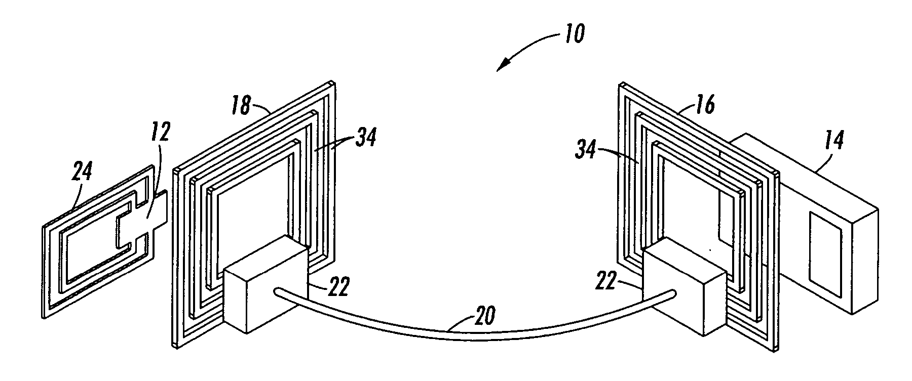
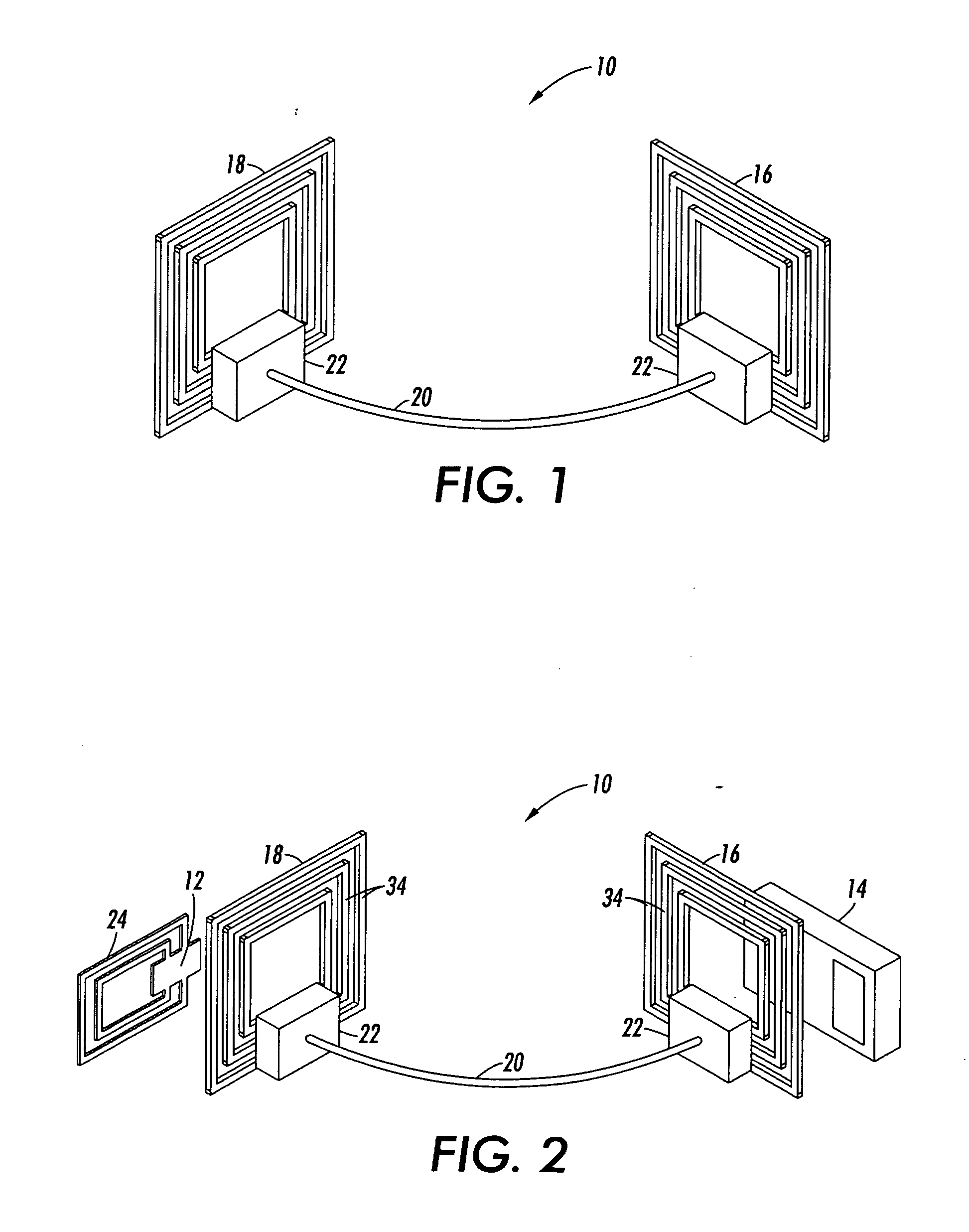
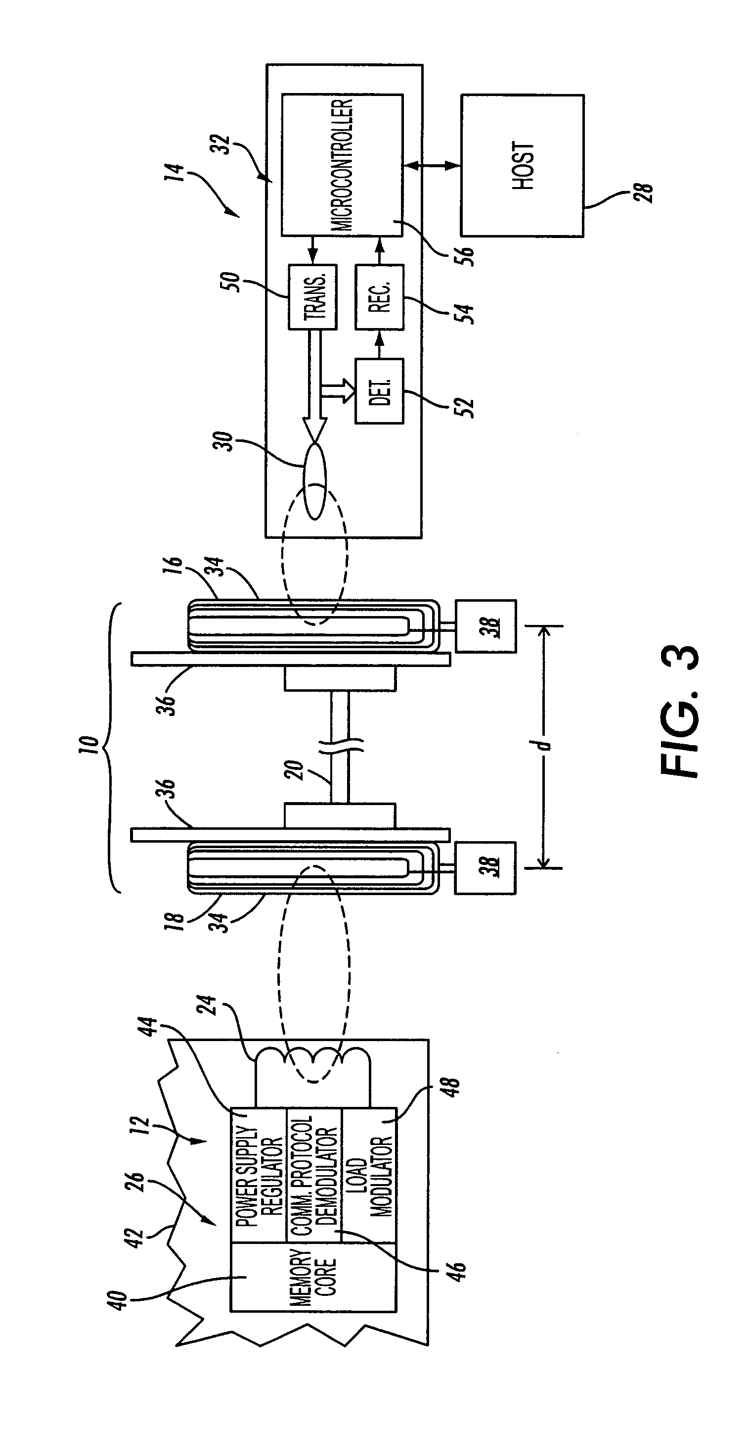
[0025] Referring to FIGS. 1-3, there is shown the basic structure of an RFID bridge antenna 10 for increasing a distance over which a tag (also known as a transponder) 12 can communicate with a reader (also known as an interrogator, transceiver, or coupler) 14. As shown in FIG. 1, the bridge antenna 10 comprises two RF antenna elements or coils 16 and 18 spaced apart from one another and electrically coupled together by an electrical conductor 20. As shown in more detail in FIG. 2, one of the RF coils 16 is located proximate to the reader 14 while the other RF coil 18 is located proximate to the tag 12. The conductor 20 is preferably a flexible, low loss, shielded co-axial cable, such as a 50 ohm coax, for example, and is connected to the base of each RF coil 16, 18 using a conventional coaxial terminals 22. The tag 12 is typically attached to an object (not shown), and includes a tag antenna 24 and an integrated circuit (IC) device 26 (see FIG. 3). Stored within the IC device 26 is...


PUM


Abstract

An RFID bridge antenna is positioned between a tag antenna associated with a tag and a reader antenna associated with a reader. The bridge includes at least two RF antenna elements spaced apart from one another and coupled together by an electrical conductor. The first RF antenna element is located proximate to the tag antenna and the second RF antenna element is located proximate to the reader antenna. An electromagnetic carrier signal transmitted by the reader antenna is received by one of the RF antenna element and retransmitted to the tag antenna by the other RF antenna element, increasing the distance over which the tag can communicate with the reader. Where the tag is attached to a packaged object, the RFID bridge antenna may be included in the package to allow wireless data communication between the tag and a reader. The reader may also be located external to the package. For example, one of the RF antenna elements may be attached to a label on the package, allowing data stored in the tag to be extracted by the external reader. The object may be a module, also known as a customer replaceable unit (CRU), and the tag may be configured as a customer replaceable unit monitor (CRUM). The module may take the form of a container having a closure cap equipped with a tag and the container may be stored in a cabinet along with an RFID bridge antenna mounted on the cabinet door to establish data communication between the tag and a reader.

Description

BACKGROUND [0001] A common trend in machine design, particularly in the office equipment industry, is to organize a machine on a modular basis, wherein certain distinct subsystems of the machine are bundled together into modules which can be readily removed from the machine and replaced with new modules of the same or similar type. A modular design facilitates great flexibility in the business relationship with the customer. By providing subsystems in discrete modules, also known as “customer replaceable units” or CRUs, visits from a service representative can be made very short, since all the representative has to do is remove and replace a defective module. Actual repair of the module may take place remotely at the service provider's premises. Further, some customers may wish to have the ability to buy modules “off the shelf,” such as from an equipment supply store. Indeed, it is possible that a customer may lease the machine and wish to buy a supply of modules as needed. Further,...

Claims


Application Information

Patent Timeline
IPC IPC(8): G08B13/14
CPCG06K7/0008G06K19/0723G06K17/0022G06K7/10178H01Q1/24G06K19/07
Inventor PHIPPS, WILLIAMRODRIGUEZ, ALBERTOBELL, SCOTT J.ROMMELMANN, HEIKO
Owner XEROX CORP
Learn More