Low profile metal-surface mounted RFID tag antenna

a metal surface mounted, low-profile technology, applied in the direction of instruments, electrical signalling details, burglar alarm mechanical actuation, etc., can solve the problems of inability to read rfid tags, inability to capture data and power from readers, large area and height, etc., to achieve convenient operation, convenient operation, and compact size

Active Publication Date: 2012-05-01
IOWA STATE UNIV RES FOUND
View PDF21 Cites 40 Cited by
  • Summary
  • Abstract
  • Description
  • Claims
  • Application Information

AI Technical Summary

Benefits of technology

[0015]It is a further object, feature, or advantage of the present invention to provide an RFID tag which may be applied to metal or other types of conductive surfaces.
[0016]It is a still further object, feature, or advantage of the present invention to provide an RFID tag which is economical to manufacture and use.
[0017]One or more of these and / or other objects, features, or advantages of the present invention will be clear from the specification and claims that follow.
[0018]The present invention relates to an RFID tag mountable on metal. The RFID tag uses a slotted inverted-L antenna. The antenna provides an approximately omnidirectional radiation pattern and sufficient bandwidth in the 900 MHz ISM (902˜928 MHz) frequency band. The antenna may have a compact size, a low profile, and good reading range in all directions. The antenna may be built on an inexpensive dielectric layer, such as foam. The fabrication process may use silver printing and folding to limit production costs.
[0019]According to one aspect of the present invention, a passive RFID tag suitable for attachment to an electrically conductive surface is provided. The passive RFID tag includes a dielectric substrate, an RFID chip for storing data, and an RFID antenna structure operatively connected to the RFID chip wherein the RFID antenna structure comprises a slotted inverted L-shape.
[0020]According to another aspect of the present invention, a method of manufacturing a passive RFID tag is provided. The method includes forming an antenna structure on a conductive layer, the antenna structure comprising a slotted inverted L-shape. The method further includes operatively connecting an RFID chip with the antenna structure.

Problems solved by technology

One of the most significant challenges is that the RFID tag can not be read when using the commonly used dipole antennas when the tags are attached to a conductive surface.
Thus the total radiated (or received) field is negligible and therefore, the RFID tag is unable to capture data and power from the reader.
This is a significant problem given that in many commercial applications it is desirable to apply the RFID tag to a metal or other type of conductive surface.
Based on this performance, the area and the height are too large.
The RFID tag antenna is a multilayer structure built on Teflon, thus making it more expensive to manufacture.
The deficiency is that the antenna needs two ground connections.
The two shorting plates to ground are in opposite direction, which increases the cost of the fabrication.
Even where such antennas demonstrate reasonable reading ranges, such antennas require relatively expensive substrate material (such as Teflon), complicated fabrication processes, thick substrates (3 mm˜4 mm) and result in RFID tag antennas which occupy relatively large areas.
Such an antenna may still be too large in size and more expensive then desired.
The cost may be relatively high and the reading range relatively low due to the high dielectric material.
However, such attempts have resulted in designs which are too large, too expensive to fabricate, too limited with respect to reading range, or in designs that otherwise adversely affect the performance of the RFID tag or its commercial viability.

Method used


Image

  • Low profile metal-surface mounted RFID tag antenna
  • Low profile metal-surface mounted RFID tag antenna
  • Low profile metal-surface mounted RFID tag antenna

Examples


Embodiment Construction

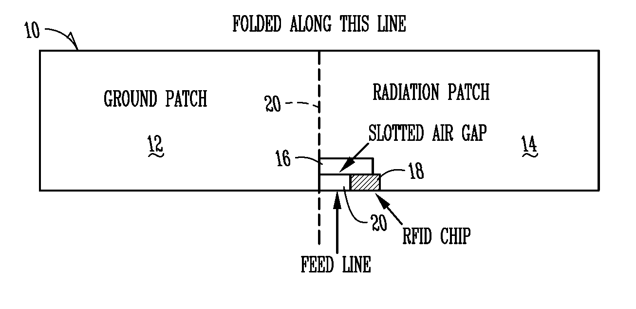
[0035]The present invention provides an RFID tag which is suitable for use on a metal or other type of conductive surface and which is economical and convenient to manufacture. By using a slotted inverted-L structure, the present invention provides a solution to this long unsolved problem with verifiable performance.

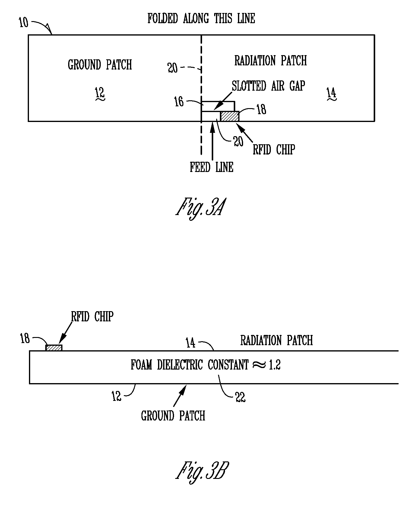
[0036]According to one aspect of the present invention a high efficiency metal-surface mounted radio frequency identification (RFID) tag antenna is provided which is operated in the ultra high frequency (UHF) band. The antenna has a slotted inverted-L shape. As used herein, the term “structure” when used to describe an antenna, describes its geometrical configuration. Thus, the antenna structure may be described as having a slotted inverted L-shape. The antenna allows for a compact size, low profile, and excellent reading range. The antenna is built on foam with 64 mils thickness and tested by a Symbol RFID handheld reader (MC9000-G) with 4 W EIRP. The reading range is m...


PUM


Abstract

A passive RFID tag suitable for attachment to an electrically conductive surface is provided. The passive RFID tag includes a dielectric substrate, an RFID chip for storing data, and an RFID antenna structure operatively connected to the RFID chip wherein the RFID antenna structure comprises a slotted inverted L-shape. A method of manufacturing a passive RFID tag includes forming an antenna structure on a conductive layer, the antenna structure comprising a slotted inverted L-shape. The method further includes operatively connecting an RFID chip with the antenna structure. A method associated with a passive RFID tag includes providing a passive RFID tag. The passive RFID tag includes a dielectric substrate, an RFID chip for storing data, and an RFID antenna structure operatively connected to the RFID chip wherein the RFID antenna structure comprises a slotted inverted L-shape. The method further includes operatively connecting the passive RFID tag to a conductive surface.

Description

FIELD OF THE INVENTION[0001]The present invention relates to RFID tags, and more particularly to a low profile metal-surface mounted antenna suitable for use in RFID tags.BACKGROUND OF THE INVENTION[0002]As one of the fastest growing sectors of automatic identification procedures (Auto-ID), contactless radio frequency identification (RFID) technology has been broadly applied to enterprise supply chain management and other applications.[0003]A typical RFID system includes a RFID reader or interrogator, a RFID chip and a RFID tag antenna. The RFID chip and the RFID tag antenna are typically packaged together to form an RFID tag. The RFID chip stores data which often includes identifying information. The data may be retrieved by a RFID reader through the RFID tag antenna.[0004]A low cost passive RFID transponder or RFID tag does not include any internal power supply. In such a system, the RFID reader sends both information and power to the RFID tag. The RFID tag receives the power and ...

Claims


Application Information

Patent Timeline
Patent Type & Authority Patents(United States)
IPC IPC(8): G08B13/14
CPCG06K19/07749G06K19/07771G06K19/07786
Inventor ZHAN, SANYIWEBER, ROBERT J.
Owner IOWA STATE UNIV RES FOUND
Why Eureka
Try Eureka