Multiband RFID tag

a multi-band, wireless technology, applied in the direction of antenna details, electrically long antennas, antennas, etc., can solve the problems of limited uhf range, limited range, spatial field pattern coverage, etc., and achieve the effect of not teaching operation with sensitivity

Inactive Publication Date: 2011-03-24
NEW JERSEY MICROSYST
View PDF3 Cites 41 Cited by
  • Summary
  • Abstract
  • Description
  • Claims
  • Application Information

AI Technical Summary

Problems solved by technology

Prior art RFID tags contain antenna and other structures that limit the performance in range, spatial field pattern coverage, and performance on metal.
For instance, the antenna structure in the Brown and Lawrence application US2007/0290941

Method used


Image

  • Multiband RFID tag
  • Multiband RFID tag
  • Multiband RFID tag

Examples


Embodiment Construction

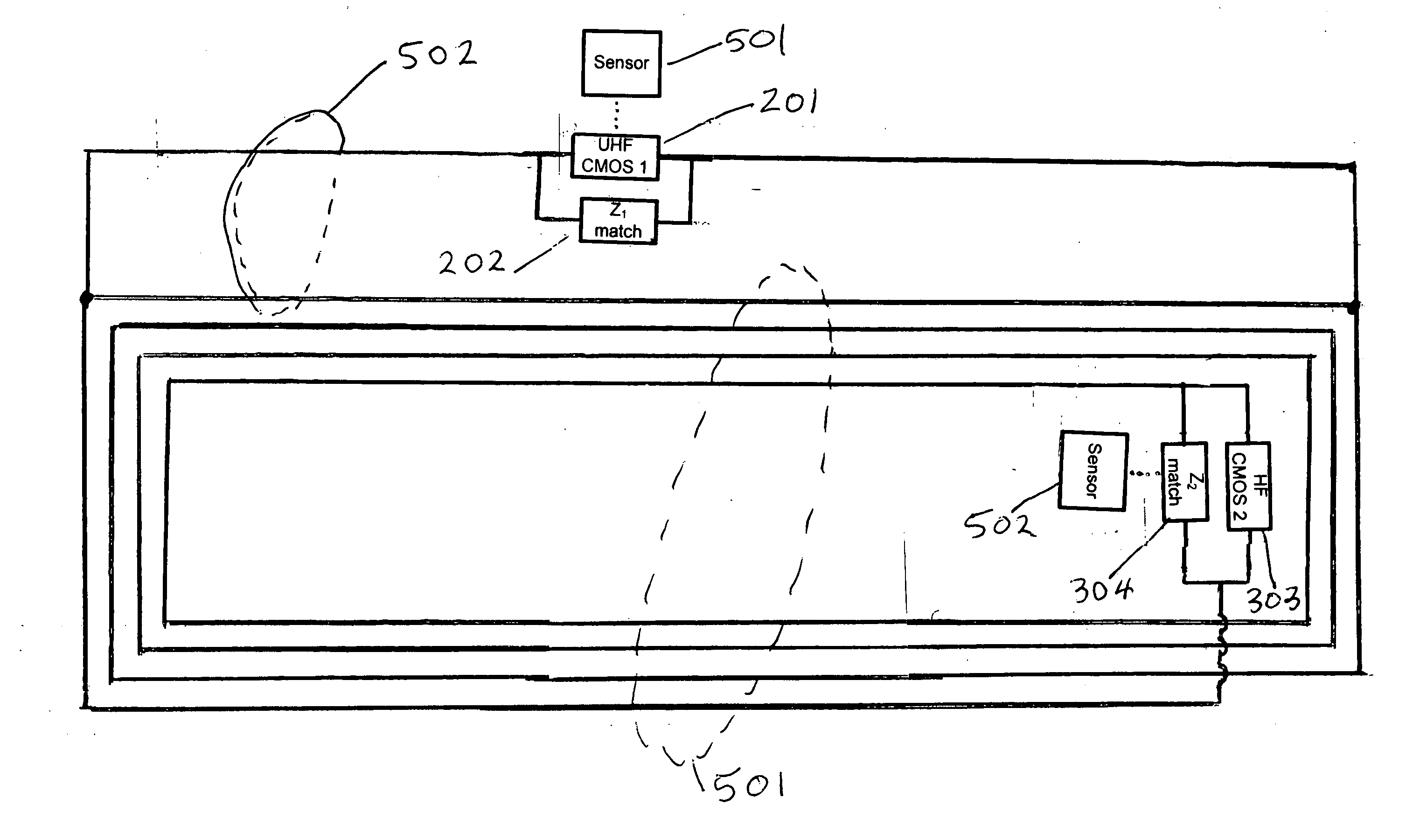
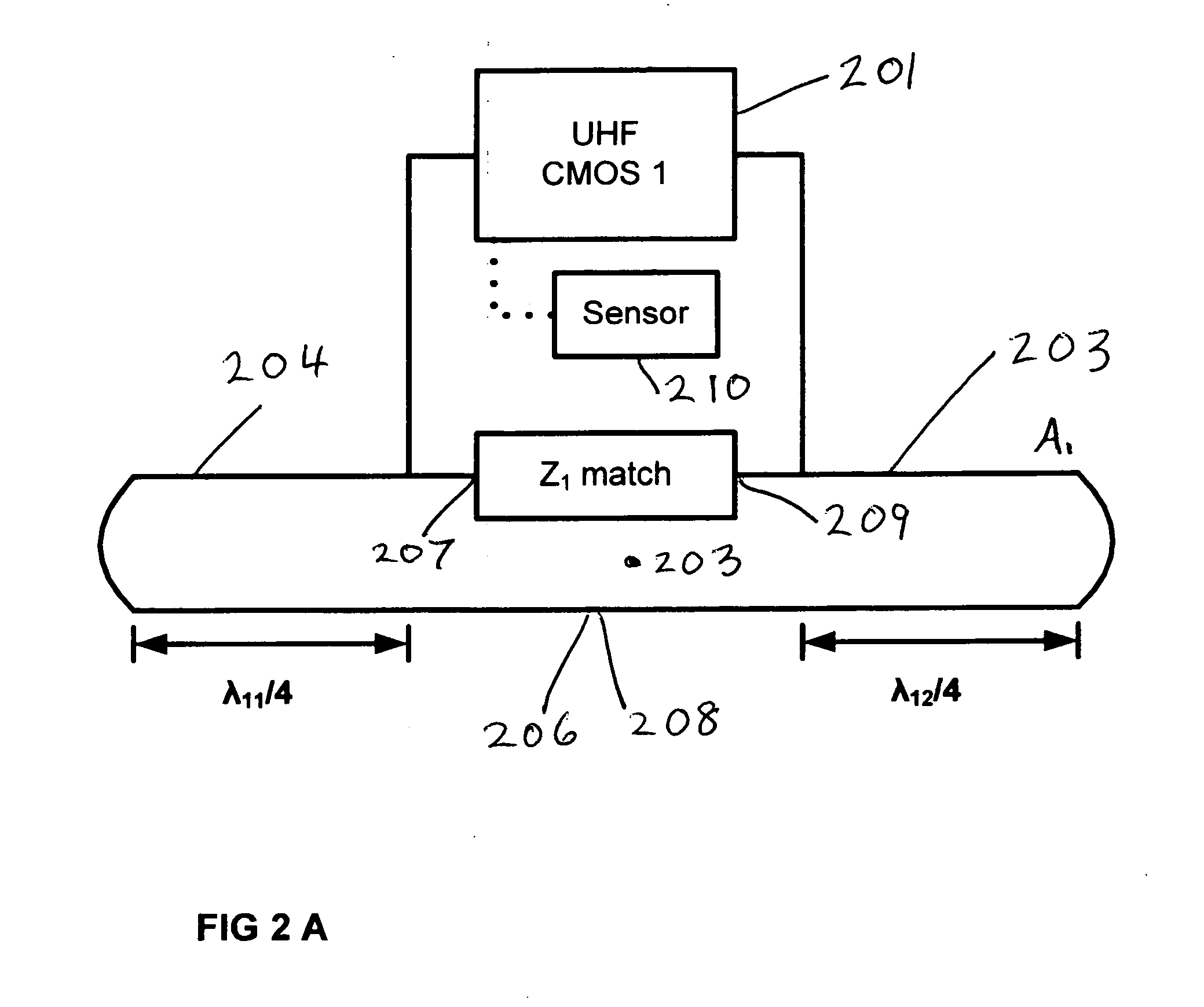
[0019]The present invention is an RFID tag with antenna structures sensitive to (a) incident electromagnetic radiation in the UHF frequency range, and (b) magnetic induction fields in the LF and HF frequency range.

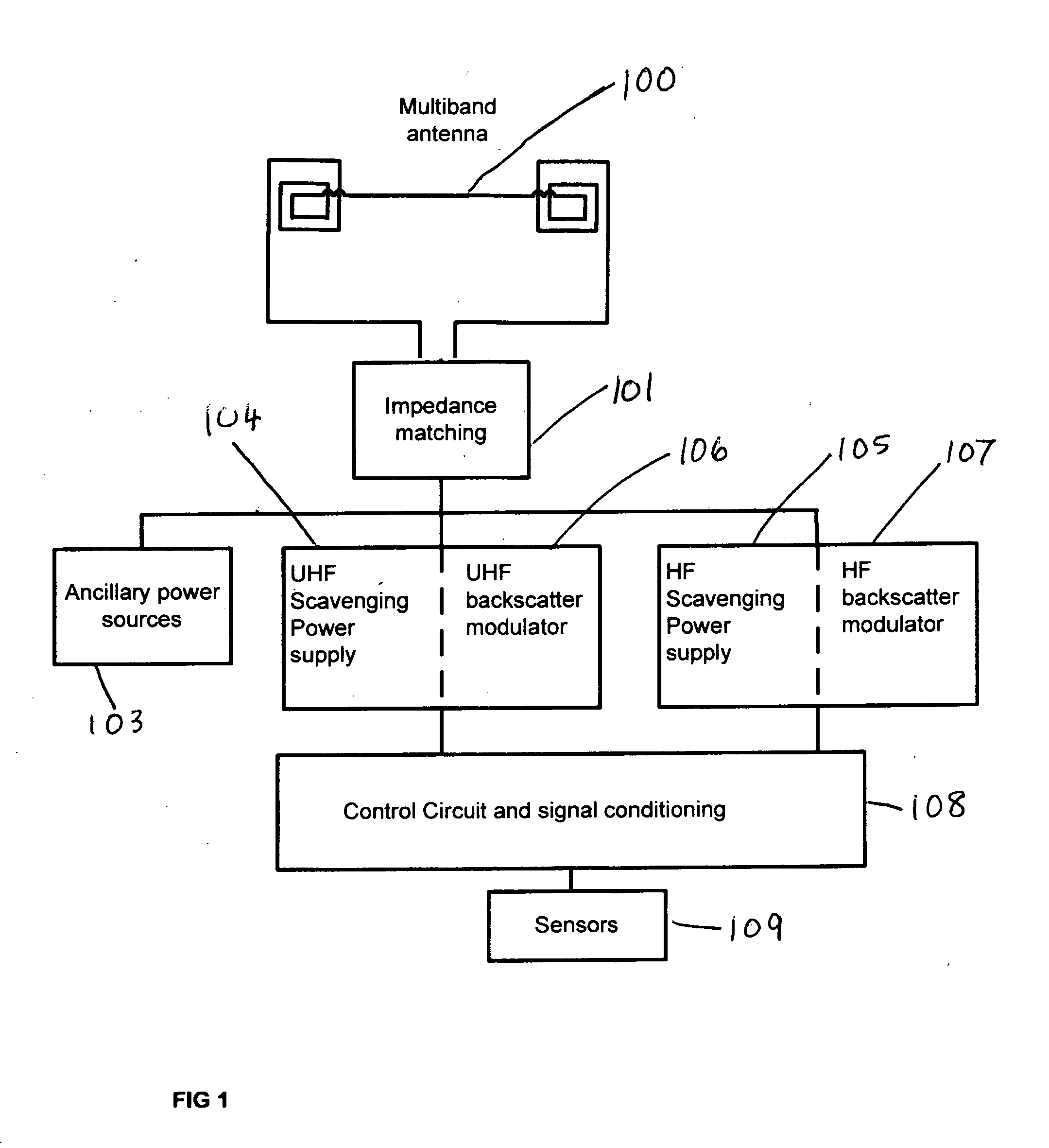
[0020]FIG. 1 is a schematic illustration of the tag architecture with the multiband antenna 100 connected through the impedance matching circuits 101 to separate UHF and lower frequency RF and communication protocol circuits. The scavenging power supplies 104, 105 supplied by the incident RF energy contains voltage multiplier circuits to increase the voltage to the circuits above the threshold required for reliable operation. This voltage typically is in the range of 1.5 to 3.3 Volts for current state of the art micropower circuitry.

[0021]The lower frequency operational range is referred to as HF in this patent. The frequencies for the application of this patent in the lower frequency range is 100 KHz up to 300 MHz. The higher frequency range for the RFID tag structures in...


PUM


Abstract

An RFID tag communicating with a wireless reader interrogator on more than one frequency band. In one embodiment the tag contains independent sensor circuits for a ultra high frequency UHF band and a lower frequency band. The UHF antenna element used in the tag is a double-resonant antenna typically operating in the 860-960 MHz frequency range providing both near and far field sensitivity. Separate resonant antenna structures a the lower frequency band is connected in series with the UHF antenna substructure. The high frequency HF antenna element contains a coil for magnetic induction pickup of signals typically in the 7-14 MHz frequency band but can also be used for the entire spectral range 100 KHz to 100 MHz. The tag antenna is an integrated structure providing for operation in both the UHF and a lower frequency band. In a separate embodiment the tag is configured with the UHF double-dipole antenna structure only and operates in a single UHF band.

Description

FIELD OF THE INVENTION[0001]This invention relates to wireless tag devices that include an integral antenna structure for scavenging power from RF incident or ambient radiation. The invention relates to wireless tags particularly those that rely on near-field inductive coupling and far-field electromagnetic coupling means of extracting power from remote RF power sources and backscattering RF signal to a remote reader.LIST OF FIGURES[0002]The accompanying drawings illustrate the present invention and enable a person skilled in the art to make and use the invention.[0003]FIG. 1 Multiband RFID sensor tag architecture[0004]FIG. 2(a) UHF antenna substructure[0005]FIG. 2(b) UHF antenna structure with series inductor[0006]FIG. 3 HF antenna substructure[0007]FIG. 4 HF and UHF antenna substructures combined[0008]FIG. 5 HF and UHF antenna integrated into a single structureDESCRIPTION OF THE RELATED ART[0009]RFID tags and systems are utilized in many different industries and have a variety of ...

Claims


Application Information

Patent Timeline
IPC IPC(8): H01Q11/12
CPCH01Q7/00H01Q1/2225
Inventor CARR, WILLIAM N.
Owner NEW JERSEY MICROSYST
Why Eureka
Try Eureka