
Multiple-antenna device having an isolation element

a technology of isolation element and antenna device, applied in the field of wireless communication, can solve the problems of interference problems, difficulty in achieving high isolation between antennas, and additional problems

Active Publication Date: 2008-06-12
QUALCOMM INC
View PDF8 Cites 52 Cited by
  • Summary
  • Abstract
  • Description
  • Claims
  • Application Information

AI Technical Summary

Benefits of technology

The present invention provides a printed circuit board with multiple antennas that have electromagnetic isolation between them. The device includes a ground plane and non-conductive support members between the antennas and the ground plane. The antennas are connected to separate feed points on the printed circuit board. The technical effect of this invention is that it allows for more efficient and reliable wireless communication in a compact device.

Problems solved by technology

Furthermore, enclosing antenna modules and repeater circuitry within the same package is desirable for convenience, manufacturing cost reduction and the like, but such packaging can give rise to interference problems.
Additional problems arise however when packaging repeater antennae and circuitry in close proximity.
First, it becomes difficult to achieve high isolation between antennae due solely to the close physical proximity even where directional antennae are used.
Simply put, as the antennae are placed closer together, the more likely the antennae will couple energy into each other, which reduces the isolation between the sides of the repeater.
Maintaining an omni or semi-omni directional antenna pattern becomes difficult since overlapping radiation patterns of antennae which are placed close to each other tend to generate interference effects.
While the use of direction antenna can benefit the repeater in terms of increased range and reduced wireless signal variation due to Raleigh fading effects, directional antennas are not typically used for indoor applications, due to the requirement for directional alignment, which is beyond the capability or desire of the average user.
Such cancellation however can be expensive in that additional circuitry is required, and can be computationally expensive in that such cancellation can result in the introduction of a delay factor in the repeater or alternatively can require the use of more expensive and faster processors to perform the cancellation function.

Method used


Image

  • Multiple-antenna device having an isolation element
  • Multiple-antenna device having an isolation element
  • Multiple-antenna device having an isolation element

Examples


Embodiment Construction

[0024]The instant disclosure is provided to further explain in an enabling fashion the best modes of performing one or more embodiments of the present invention. The disclosure is further offered to enhance an understanding and appreciation for the inventive principles and advantages thereof, rather than to limit in any manner the invention. The invention is defined solely by the appended claims including any amendments made during the pendency of this application and all equivalents of those claims as issued.

[0025]It is further understood that the use of relational terms such as first and second, and the like, if any, are used solely to distinguish one from another entity, item, or action without necessarily requiring or implying any actual such relationship or order between such entities, items or actions. It is noted that some embodiments may include a plurality of processes or steps, which can be performed in any order, unless expressly and necessarily limited to a particular or...


PUM


Abstract

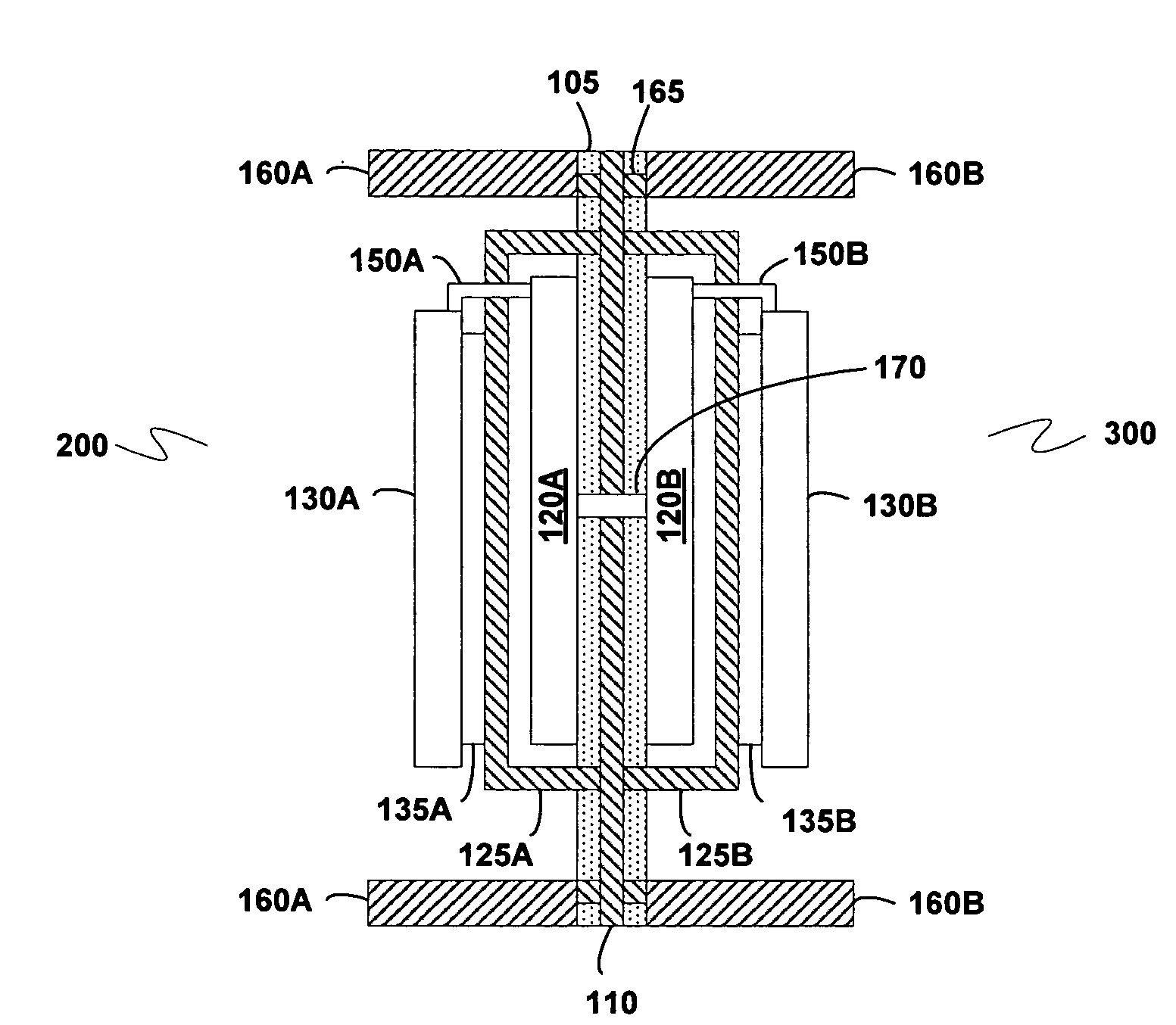
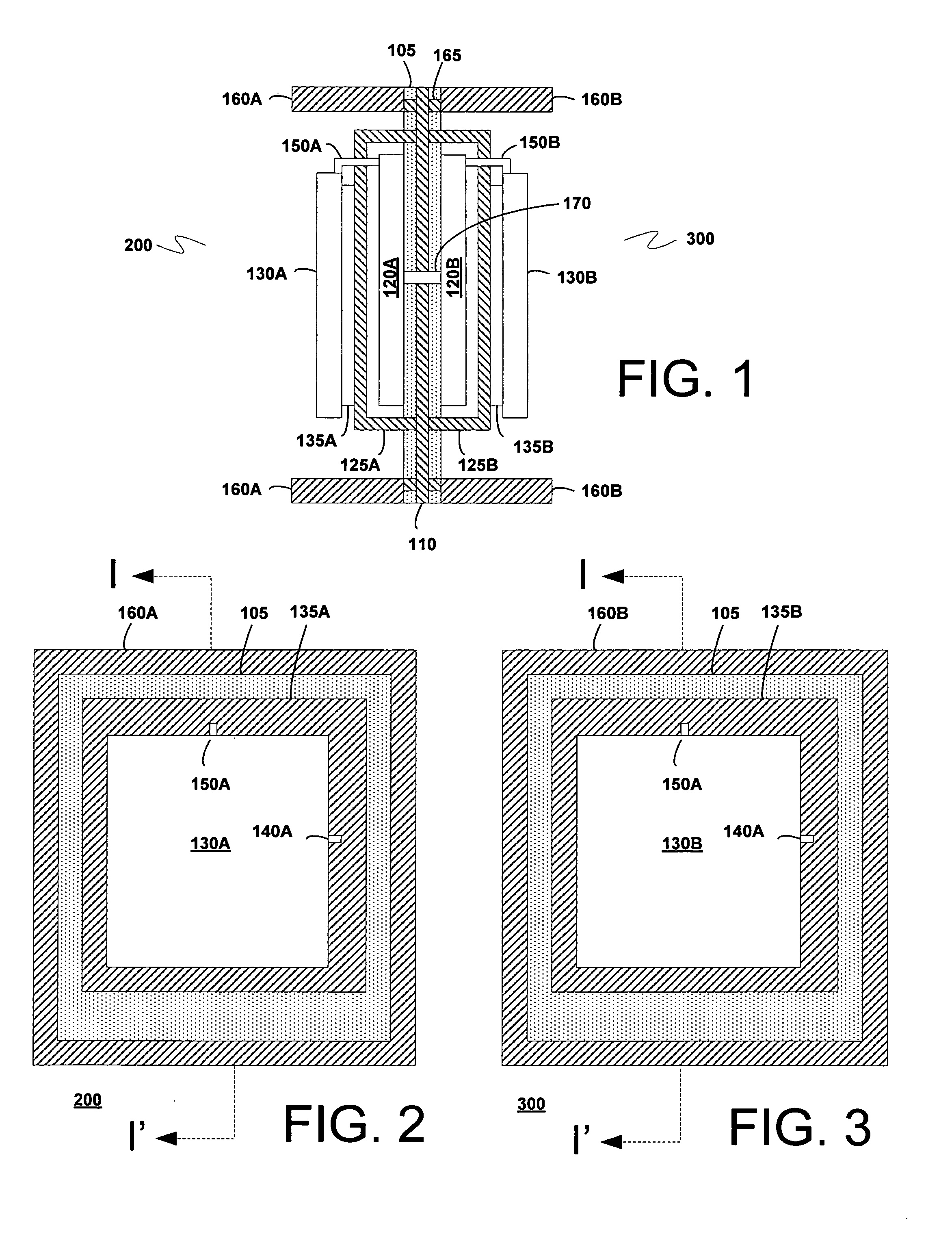
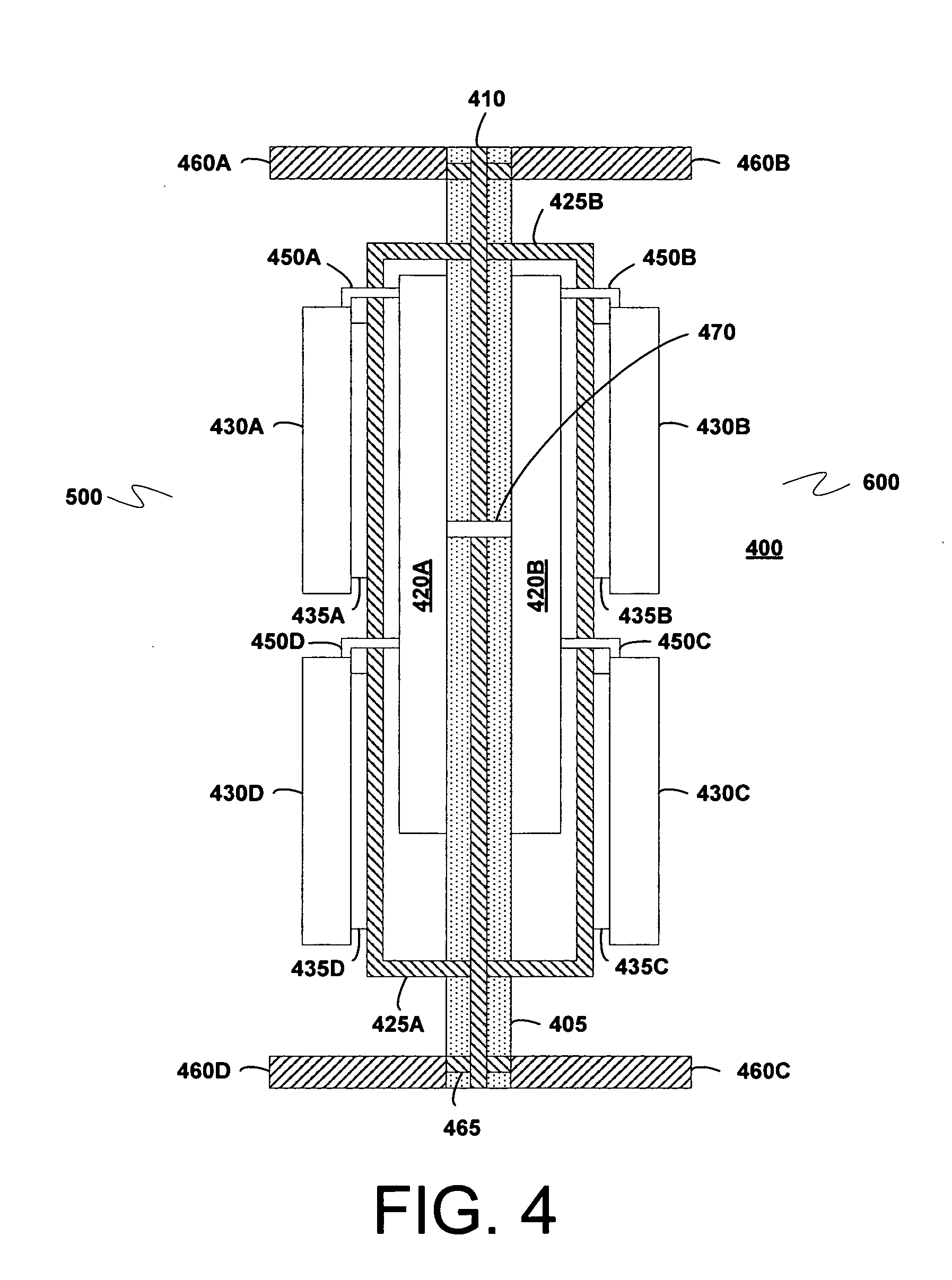
A multiple-antenna device is provided, comprising: a printed circuit board having a ground plane configured to provide electromagnetic isolation between a first side of the printed circuit board and a second side of the printed circuit board; a first non-conductive support member formed over the first side of the printed circuit board; a second non-conductive support member formed over the second side of the printed circuit board; a first antenna formed over the first non-conductive support member; and a second antenna formed over the second non-conductive support member, wherein the first antenna is electrically connected to a first feed point on a first portion of the printed circuit board that is not connected to the ground plane, and wherein the second antenna is electrically connected to a second feed point on a second portion of the printed circuit board that is not connected to the ground plane.

Description

CROSS REFERENCE TO RELATED APPLICATIONS[0001]The present invention is related to and claims priority from U.S. Provisional Patent Application No. 60 / 869,438, filed Dec. 11, 2006, entitled “METRO WIFI RF REPEATER,” the contents of which are incorporated herein by reference.TECHNICAL FIELD[0002]The present invention relates generally to wireless communication and more specifically to an antenna configuration associated with a wireless repeater, the antenna configuration made up of closely packaged antennas having orthogonal polarization and isolation to reduce electromagnetic coupling and to provide high directivity.BACKGROUND OF THE INVENTION[0003]In a wireless communication node, such as a wireless repeater designed to operate with a wireless system capable of simultaneous transmission and reception of packets (i.e., duplex operation), the orientation of the antenna units can be important in establishing non-interfering operation as it is critical that the receiver is not desensitiz...

Claims


Application Information

Patent Timeline
Patent Type & Authority Applications(United States)
IPC IPC(8): H01Q21/00H01Q9/04H01Q5/50
CPCH01Q1/007H01Q1/38H01Q1/521H01Q1/526H01Q5/50H01Q19/10H01Q21/08H01Q21/24H01Q9/0407H01Q25/005H01Q21/00H01Q5/00H01Q1/24H01Q15/24
Inventor PROCTOR, JAMES A.GAINEY, KENNETH M.
Owner QUALCOMM INC
Learn More