
Image exposure apparatus

a technology of exposure apparatus and exposure chamber, which is applied in the direction of visual presentation using printers, instruments, printing, etc., can solve the problems of interrupting the reduction of overall size, increasing the number of components to be assembled, so as to reduce the overall size

Inactive Publication Date: 2008-06-12
NORITZ CORP
View PDF9 Cites 0 Cited by
  • Summary
  • Abstract
  • Description
  • Claims
  • Application Information

AI Technical Summary

Benefits of technology

The solution enables flexible light source arrangement, reduces assembly complexity, and ensures accurate detection and synchronization of light beams, improving image reproduction quality and reducing the risk of color displacement, thereby enhancing the operational reliability and efficiency of the image exposure process.

Problems solved by technology

Although being used widely, this method however requires a set of fairly expensive optical components for combining the light beams and increases the number of the entire components to be assembled as yet having a limitation on the geometrical arrangement of the light sources and will hence be unfavorable for reduction of the overall size.
If the optical sensor units are provided corresponding to the three light beams, the number of the components will increase and thus interrupt the reduction of the overall size.
If any of the three light beams is not detected, the reproduction of an image will be unsuccessful.
However, this produces the following problems.
Accordingly, as the freedom for positioning the light sources is declined, the arrangement of design will hardly be flexible and favorable in the reduction of the overall size.
Those laser devices however are different in the package size and their positioning may largely affect the overall dimensions of the apparatus.
If worse, the reproduced image will have color displacement.
Moreover, if the optical axis of any acousto-optic device employed for modulating the beam of light with a pixel data is slightly dislocated by the effect of temperature change or mechanical impact, it will critically affect the exposure action.
On the contrary, this will unfavorably require an extra sensor unit for the examination in the conventional image exposure apparatus.

Method used


Image

  • Image exposure apparatus
  • Image exposure apparatus
  • Image exposure apparatus

Examples


Embodiment Construction

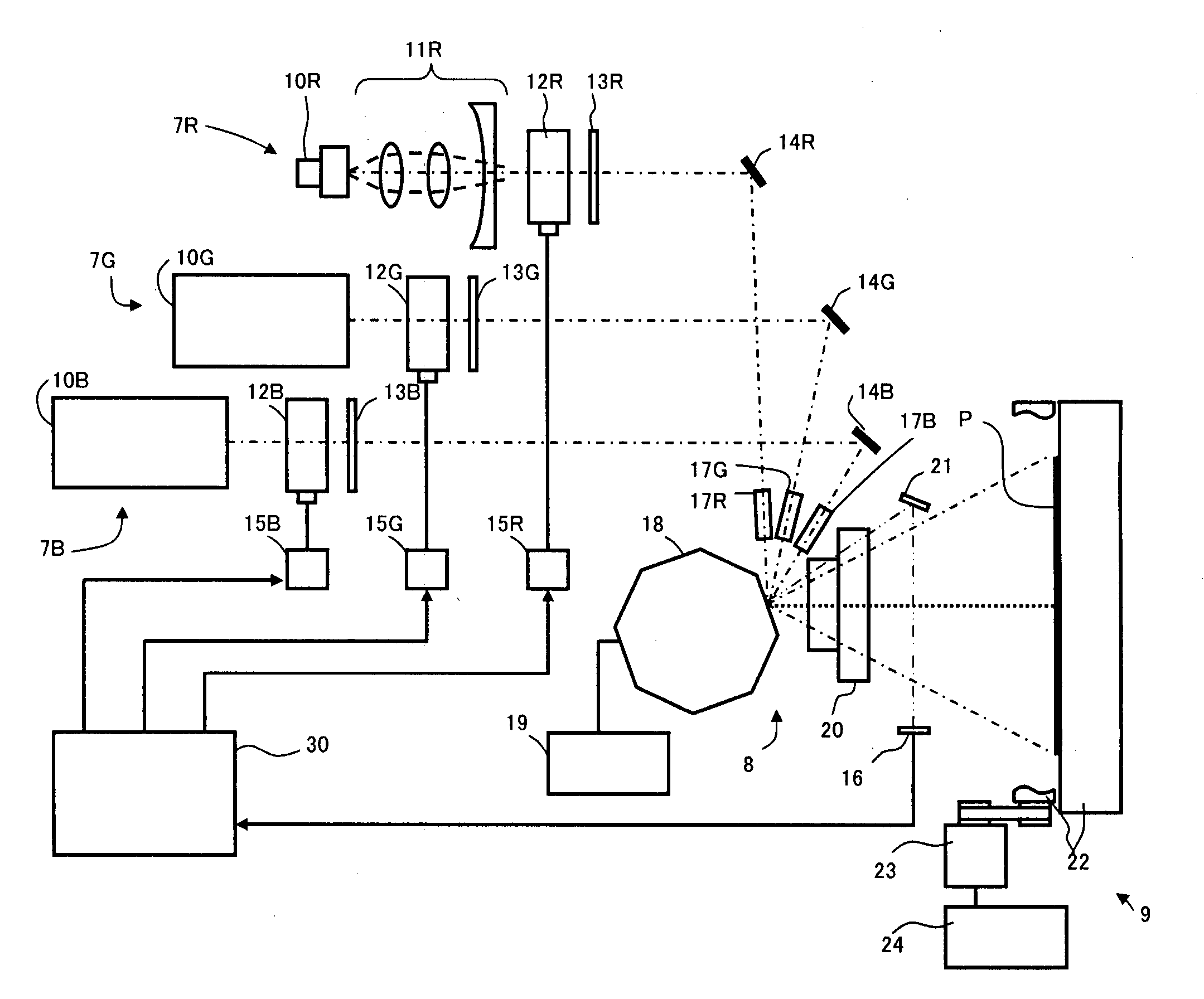
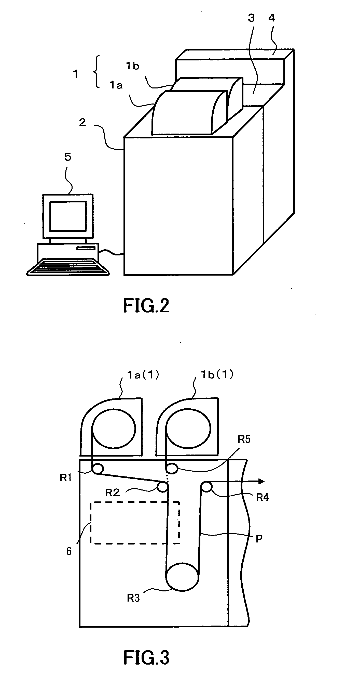
[0031]The image exposure apparatus according to this invention will now be described referring the relevant drawings. As shown in FIG. 2, a digital photographic printer is provided comprising a printed paper storage 1 where rolls of printed paper such as photosensitive materials are stored for reproducing gradations of colors corresponding to the exposure intensities and the wavelengths of light, an image generating module 2 where an image exposure apparatus of the present invention is installed for exposing the printed paper received from said printed paper storage 1 to the beams of light scanning with image data of an original image, a development module 3 for subjecting the printed paper exposed to the beams of light in the image generating module 2 to development, breaching, and fixing steps as conveying it through vessels filled with liquid agents, a drying module 4 for drying the printed paper after the development process, and a computer 5 for carrying out steps of saving and...


PUM


Abstract

An image exposure apparatus of a different angle incident type is provided having a single optical sensor unit for determining the timing for start point synchronization along the main scanning direction, an output level detecting device determining the output level of each beam of light which can be detected by the optical sensor unit, a first modulating device modulating the output level of each beam of light with a pixel data in the light path for exposure, and a second modulating device modulating the output level of each beam of light to a higher level outside of the light path for exposure than the level determined by said output level detecting device.

Description

CROSS REFERENCE TO RELATED APPLICATIONS[0001]This application is a divisional application of U.S. patent application Ser. No. 10 / 892,128, filed on Jul. 16, 2004, currently pending. The disclosure of U.S. patent application Ser. No. 10 / 892,128 is hereby incorporated by reference.BACKGROUND OF THE INVENTION[0002]1. Field of the Invention[0003]The present invention relates to an image exposure apparatus with a different angle incident light optical system which comprises a plurality of light sources for emitting light beams of different narrow band wavelengths at different angles respectively, a deflection optical system for receiving on its same reflecting surface and reflecting the light beams in the main scanning direction to scan a photosensitive material at predetermined intervals along the scanning lines for exposure, and a single optical sensor unit located outside of the light path for exposure extending from the deflection optical system to the photosensitive material for prov...

Claims


Application Information

Patent Timeline
Patent Type & Authority Applications(United States)
IPC IPC(8): G03B27/72B41J2/44B41J2/47G06K15/12H04N1/04H04N1/113
CPCB41J2/473G06K15/1209G06K15/1295G06K15/129G06K15/1219
Inventor SETO, MIKIYAYOSHIDA, KAZUHIRO
Owner NORITZ CORP
Learn More