
Illumination with optical communication method

Inactive Publication Date: 2008-06-12
FORMOLIGHT TECH
View PDF3 Cites 34 Cited by
  • Summary
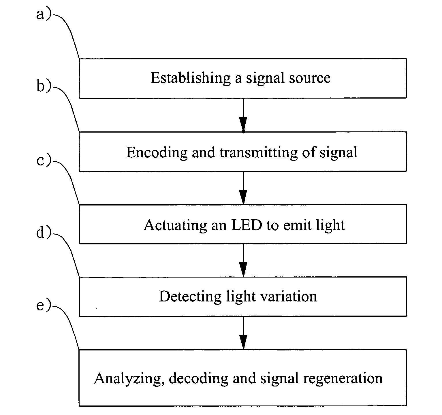
  • Abstract
  • Description
  • Claims
  • Application Information

AI Technical Summary

Benefits of technology

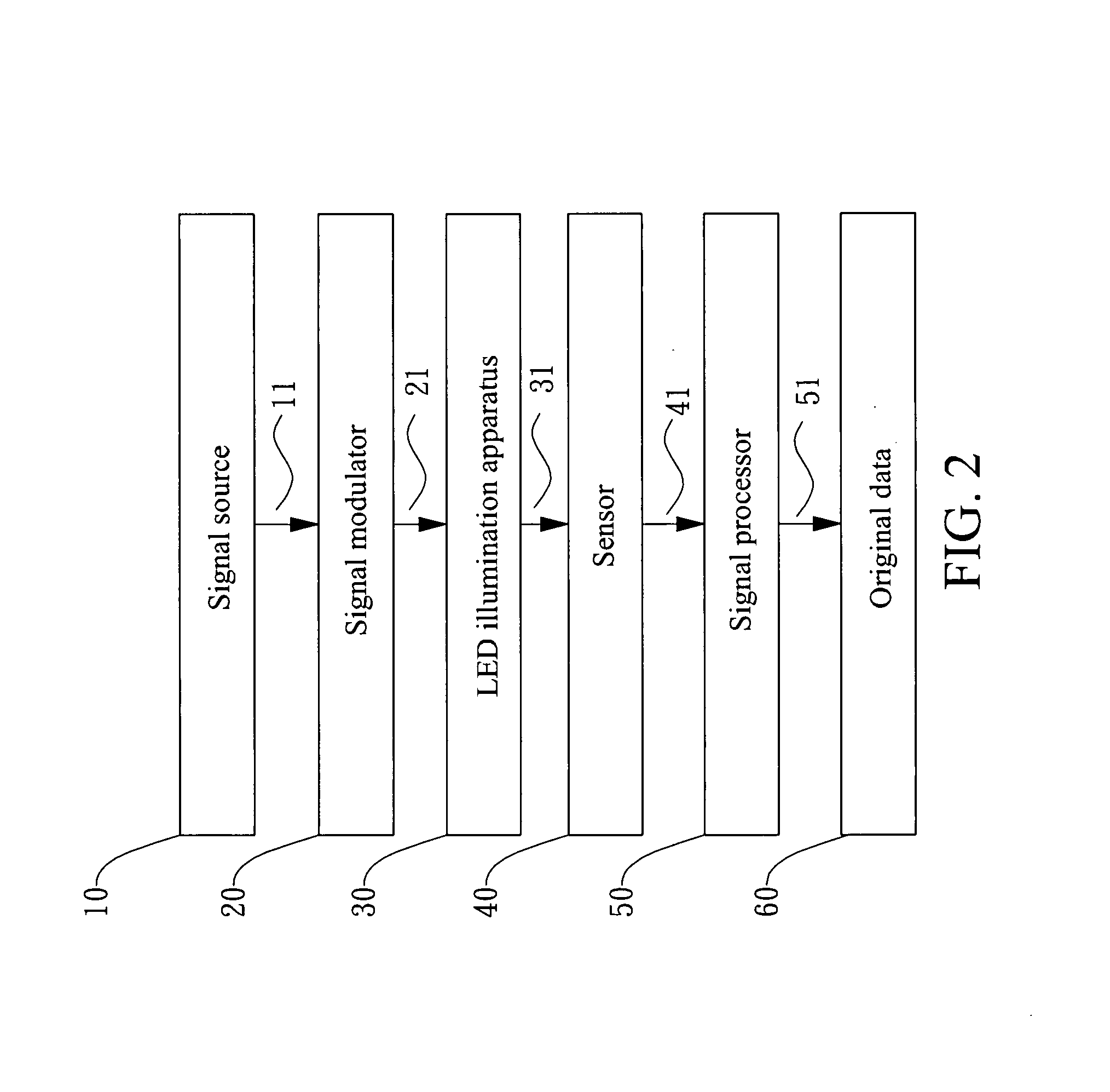
[0005]A primary objective of the present invention is to provide an illumination with optical communication method that uses an LED illumination apparatus to transmit encoded message data awaiting transmission, which then appears as the light of rapid varying intensity emitted by this transmitter. While a receiver uses a sensor to detect the light emitted by the LED illumination apparatus and analyzes a digital waveform contained therein, whereupon a signal processor decodes the digital waveform to extract the transmitted message data, thereby offering the optical communication capability to the illumination apparatus, which increases practicability and convenience of use thereof.
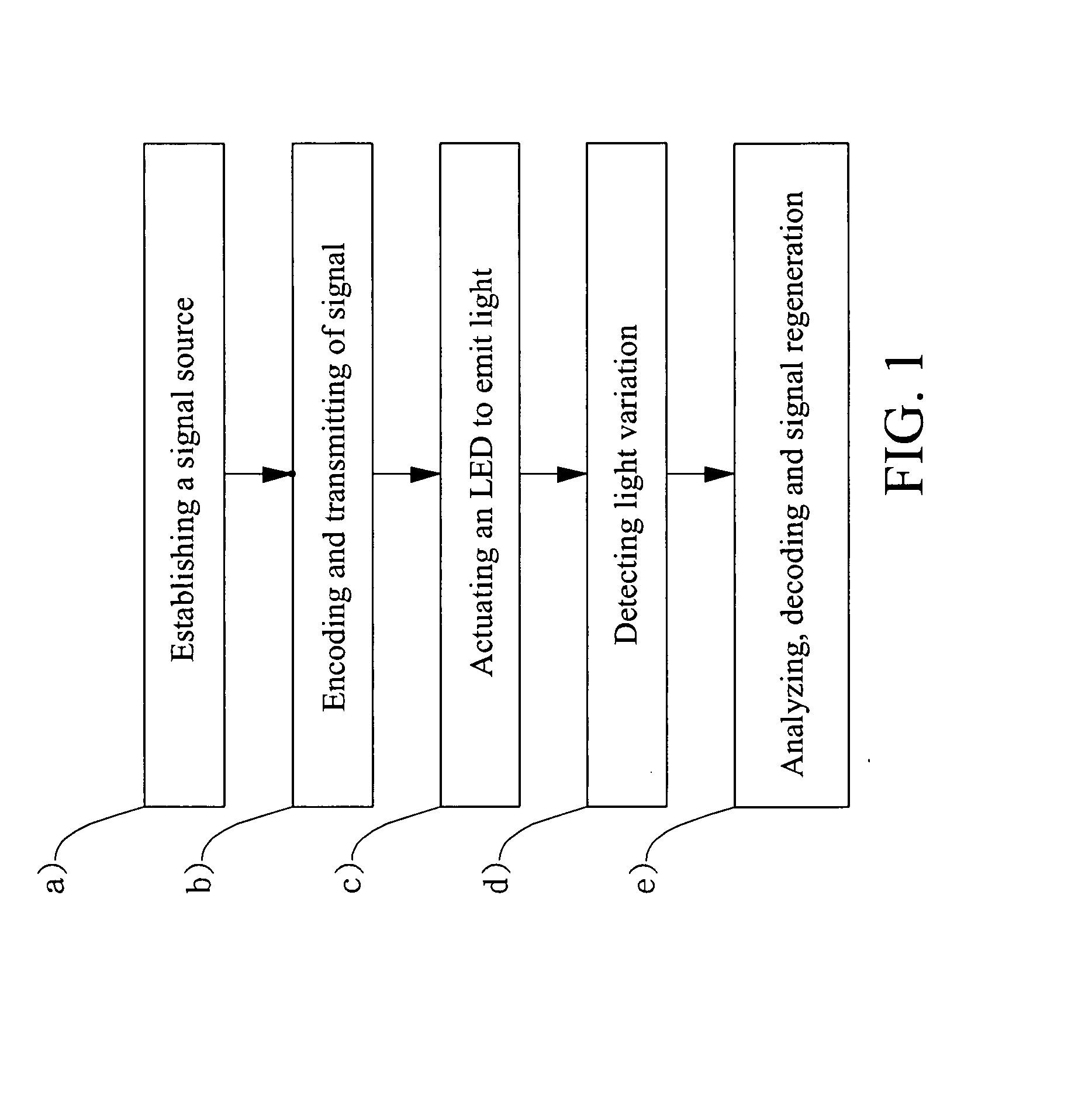
[0006]In order to achieve the aforementioned objective, the optical communication method of the present invention comprises the following steps: a), establishing a signal source: message data awaiting transmission presented in the form of a digital electric signal is established as a signal source; b), encoding and transmitting of signal: a signal modulator encodes and converts the digital electric signal awaiting transmission into an on and off control signal, and then the modulated on and off control signal is transmitted to a control circuit of an LED illumination apparatus; c), actuating an LED to emit light: the encoded and modulated on and off control signal actuates the LED illumination apparatus, which emits a modulated light; d), detecting light variation: a sensor is used to detect brightness variation in the modulated light emitted by the LED illumination apparatus, thereby obtaining a digital waveform contained therein; e), analyzing, decoding and signal regeneration: a signal processor performs analysis and decodes the digital waveform detected by the sensor, which enables the recovery of original data for use, saving or playing back thereof. Basing on such a method, a light illumination system with the communication capability can be established.

Problems solved by technology

In regard to the transmission media, the optical-fiber method to transmit optical signals is a “wired communication” method, and the optical-fiber circuit incurs the cost of material and installation.
Although its transmission distance is relatively long, it is subject to space limitations as the installation for optical fibers / cables requests.
Furthermore, the optical fibers are comparatively expensive.
Thus, in quite some situations the approach does not always stand for an ideal and complete solution.

Method used


Image

  • Illumination with optical communication method
  • Illumination with optical communication method
  • Illumination with optical communication method

Examples


Embodiment Construction

[0011]Referring to FIGS. 1 and 2, which show an optical communication method of the present invention, comprising the following steps:

[0012]a). Establishing a signal source 1: A signal source 10 is first established for signal transmission of a message data awaiting transmission 11 presented in the form of a digital electric signal (the message data awaiting transmission 11 can be a sound file, an image file, a document file or a command).

[0013]b). Encoding and transmitting of signal 2: A signal modulator 20 receives the message data awaiting transmission 11 presented in the form of a digital electric signal, whereupon the message data 11 are converted into an on and off control signals 21, and then the modulated on and off control signals 21 are transmitted to an LED (light-emitting diode) control circuit, thereby enabling the modulated on and off control signals 21 to actuate lighting up an LED illumination apparatus 30.

[0014]c). Actuating an LED to emit light 3: The modulated on ...


PUM


Abstract

The present invention provides an illumination with optical communication method that includes the following steps: a), establishing a signal source; b), encoding and transmitting of signal; c), actuating an LED to emit light; d), detecting light variation; e), analyzing, decoding and signal regeneration, which enables the recovery of original data for use, saving or playing back thereof. Basing on such a method, a light illumination system with optical communication capability can be established.

Description

BACKGROUND OF THE INVENTION[0001](a) Field of the Invention[0002]The present invention relates to an illumination with optical communication method, particularly to the one that uses the fast lighting characteristic of an LED (Light-Emitting Diode), whereby a transmitter transmits encoded message data awaiting transmission, which then appears as the light of rapid variation emitted by an LED illumination apparatus. A receiver, that uses a sensor to detect the light of varying intensity emitted by the LED illumination apparatus, analyzes the digital waveform contained therein, whereupon a signal processor decodes the digital waveform to extract the transmitted message data. Accordingly, such a method provides the present invention with both illumination and communication capabilities, which is applicable to a variety of illumination devices adopted for optical communication.[0003](b) Description of the Prior Art[0004]The prior art method of using optical fibers to transmit signals ha...

Claims


Application Information

Patent Timeline
IPC IPC(8): H04B10/00
CPCH04B10/116H04B10/1149
Inventor LIN, SHAR-MINGCHERN, MING-YANGCHOU, CHING-PAOHUANG, CHUNG-NUNGHUANG, CHIH-CHANG
Owner FORMOLIGHT TECH
Learn More