

Bipolar battery and method of manufacturing the same
a battery and bipolar technology, applied in the field of bipolar batteries, can solve the problems of gas bubbles getting trapped in micro gaps between stacked portions, dead space, deterioration of power, etc., and achieve the effect of superior battery performan
- Summary
- Abstract
- Description
- Claims
- Application Information
AI Technical Summary
Benefits of technology
Problems solved by technology
Method used
Image

Examples
first embodiment
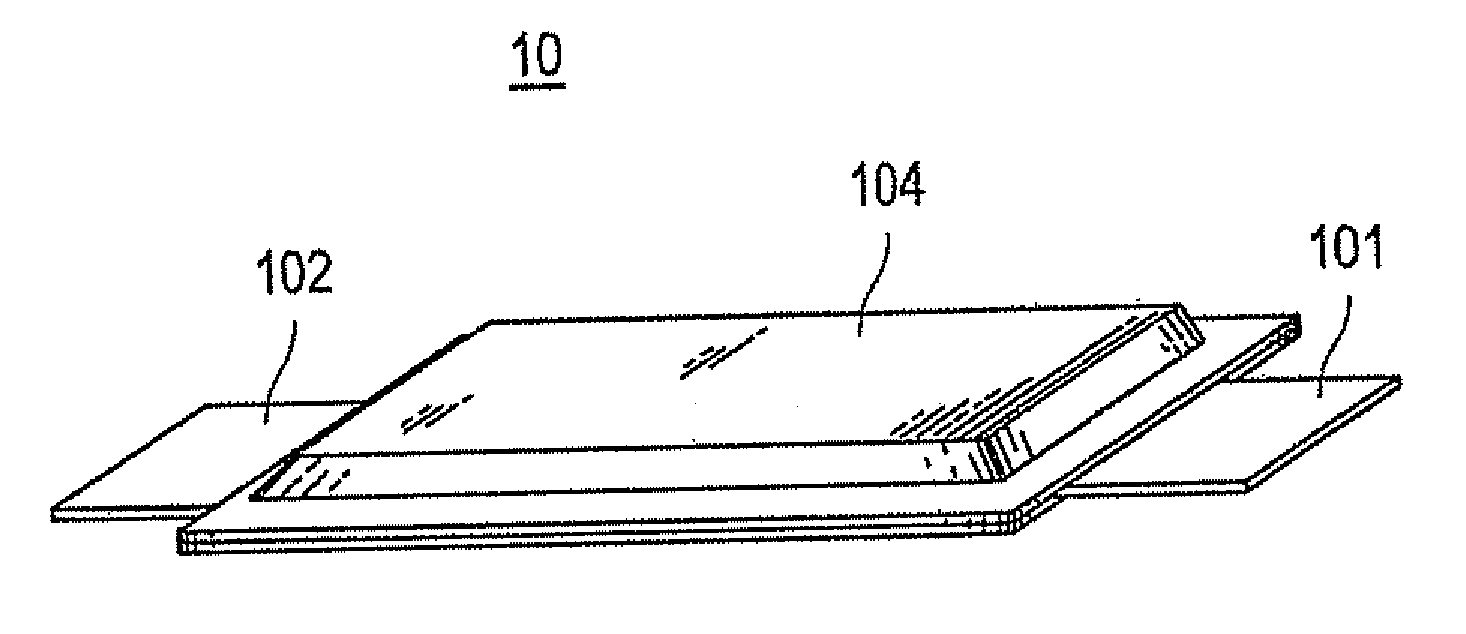
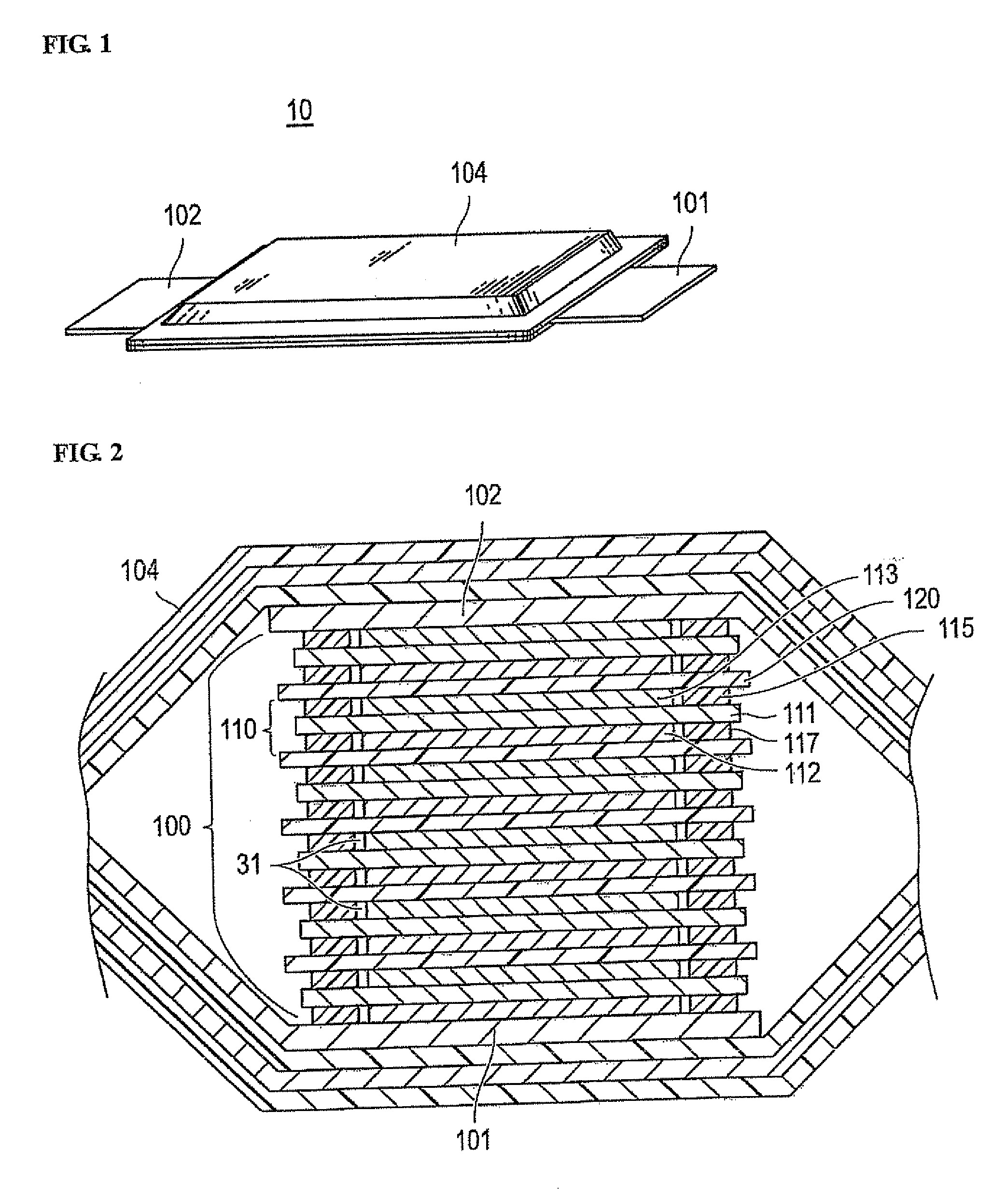
[0079]The first embodiment is next described in detail. As shown in FIG. 1, the bipolar battery 10 is constructed such that the battery element 100 is housed in an exterior case 104 to protect the battery element from external shock or environmental deterioration.
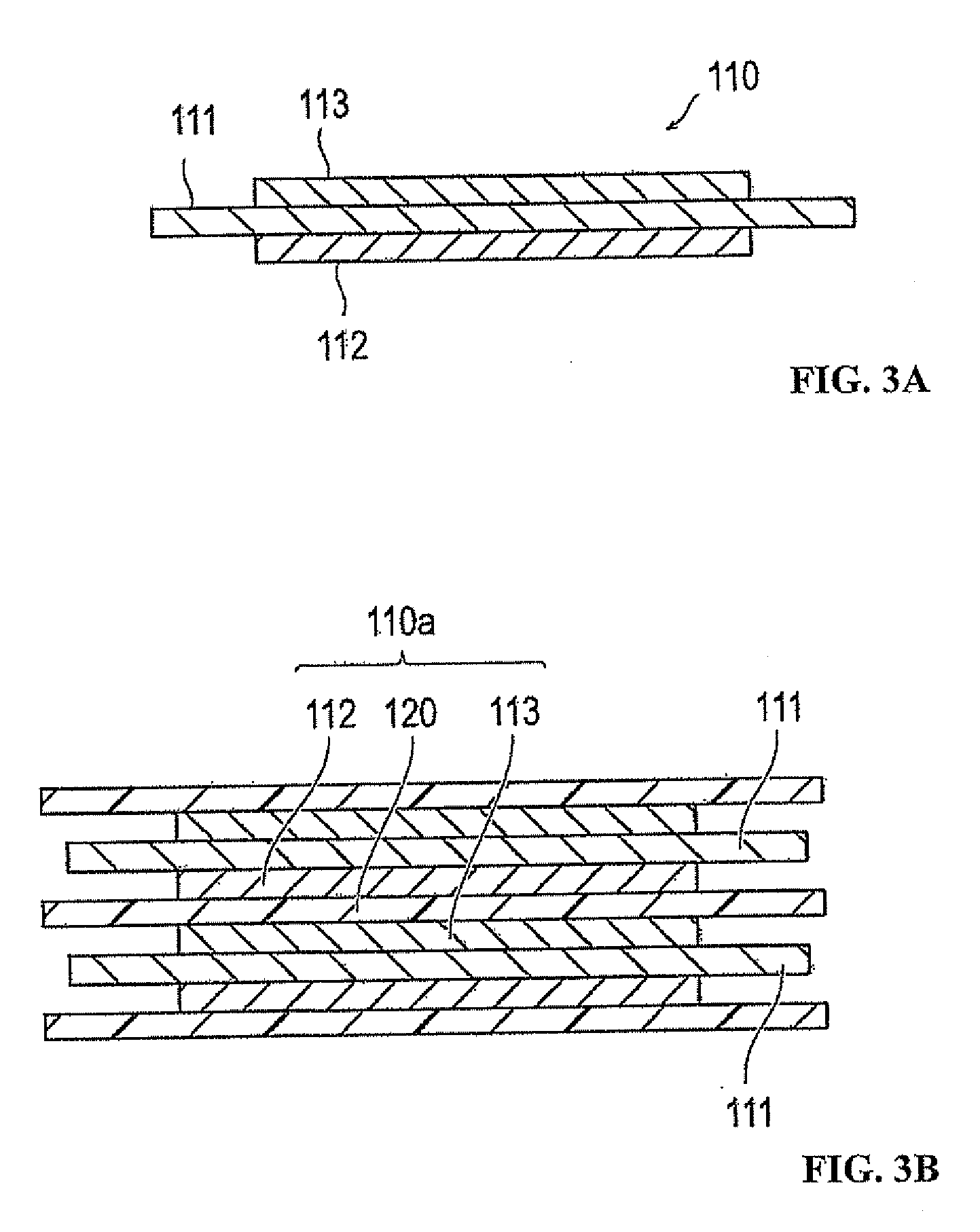
[0080]Referring to FIGS. 2 and 3A, each of the bipolar electrodes 110 is configured such that the cathode 113 is formed by attaching a cathode active material layer onto one surface of the collector 111. The anode 112 is formed by attaching an anode active material layer onto the opposite surface of the collector 111. Referring to FIG. 3B, a unit battery layer 110a is formed by the cathode 113, the electrolyte layer 120 and the anode 112. The unit battery layer 110a is fitted between two adjacent collectors 111. The number of unit battery layers 111a in a stack is determined by a required voltage.
[0081]Because the collector 111 passes an electron but blocks an ion, the collector 111 is also referred to as an ion barrier. Th...
second embodiment
[0160]FIGS. 25A and 25B are plan views illustrating the charging part 20 in accordance with the bipolar battery, wherein material storage parts 22 and 23 are arranged opposing the gap portion 21.
[0161]The second embodiment differs from the first embodiment in that the material storage parts 22 and 23 storing the material supplied to the gap portion 21 are provided. In the second embodiment, the charging part 20 is provided with the material storage parts 22 and 23, which store the material supplied to the gap portion 21. The material storage parts 22 and 23 are arranged opposing the gap portion 21. The material storage part 22 shown in FIG. 25A has a rectangular shape and is disposed at a slight distance from ends of the coated sealing materials 114 while opposing the gap portion 21. The material storage parts 23 shown in FIG. 25B have a substantially circular shape and are arranged integrally with the ends of the coated sealing materials 114 so as to form the gap portion 21. Any sh...
third embodiment
[0164]Referring to FIG. 26, the sealing materials 114 and 116 used as the charging material of the third embodiment are thermosets. The charging part 20 includes the uncured part 24, which permits the inner space 31 to communicate with the outside when stacking the bipolar electrodes 110. The uncured part 24 is then hardened after exhausting the residual gas 30 from the inner space 31. A micro gap exists in the material itself of the uncured part 24, or between the uncured part 24 of the exhaust part 32 and the separator 121. The exhausting operation of the exhaust part 32 is complete when the uncured part 24 is hardened.
[0165]The thermosetting charging materials 114 and 116 may be made from common epoxy resin. Although the gas is introduced when alternately stacking the bipolar electrodes 110 and the electrolyte layers 120, the residual gas in the inner space 31 is exhausted to the outside of the inner space 31 through the micro gap existing in the uncured part 24 of the exhaust pa...
PUM
| Property | Measurement | Unit |
|---|---|---|
| Shape | aaaaa | aaaaa |
Abstract
Description
Claims
Application Information