Multiple-Input Multiple-Output Wireless Antennas

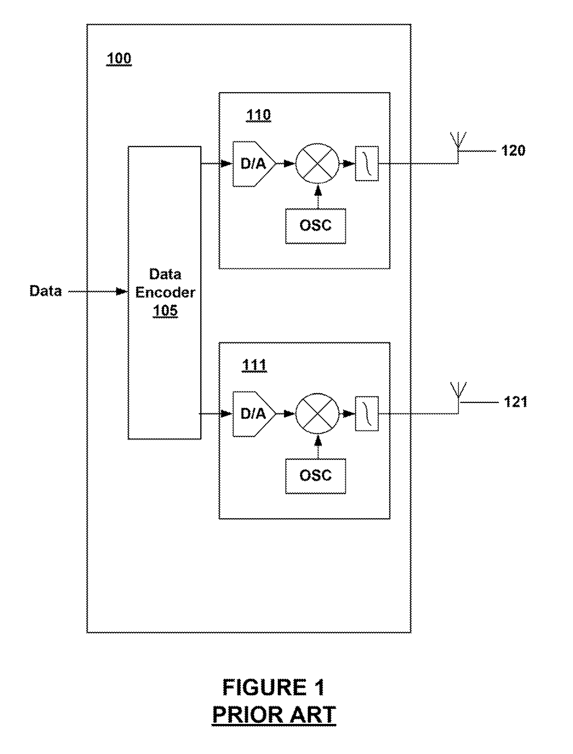
a wireless antenna and multi-input technology, applied in the field of wireless communication, can solve the problems of reducing the data rate of communication, affecting the reliability of communication, and the wireless link, so as to increase the capacity of the mimo system, and reduce the correlation between received signals

Active Publication Date: 2008-06-12
ARRIS ENTERPRISES LLC
View PDF58 Cites 48 Cited by
  • Summary
  • Abstract
  • Description
  • Claims
  • Application Information

AI Technical Summary

Benefits of technology

[0015]MIMO wireless technology uses multiple antennas at the transmitter and receiver to produce capacity gains over single-input single-output (SISO) systems using the same or approximately equivalent bandwidth and transmit power. The capacity of a MIMO system generally increases linearly with the number of antennas in the presence of a scattering-rich environment. MIMO antenna design reduces correlation between received signals by exploiting various forms of diversity that arise due to the presence of multiple antennas.

Problems solved by technology

For example, a wireless link in an Institute of Electrical and Electronic Engineers (IEEE) 802.11 network may be susceptible to interference from other access points and stations, other radio transmitting devices, and changes or disturbances in the wireless link environment between an access point and remote receiving node.
In some instances, the interference may degrade the wireless link thereby forcing communication at a lower data rate.
The interface may, however, be sufficiently strong as to disrupt the wireless link altogether.
Diversity schemes are generally lacking in that typical omnidirectional antennas are vertically polarized.
Vertically polarized radio frequency energy does not travel as efficiently as horizontally polarized energy with respect to a typical wireless environment (e.g., a home or office).
These wands are easily susceptible to breakage or damage.
Omnidirectional antennas in a diversity scheme, too, may create interference amongst one another or be subject to the same interference source due to their physical proximity.
As such, a diversity antenna scheme may fail to effectively reduce interference in a wireless link.
Phased array antennas are prohibitively expensive to manufacture.
Phased array antennas, too, require a series of complicated phase tuning elements that may easily drift or otherwise become maladjusted over time.
The large number of whip antennas used in a prior art MIMO antenna system not only increase the probability that one or more of the antennas may be damaged during use but also creates unsightly ‘antenna farms.’ Such ‘farms’ are generally unsuitable for home or business applications where access points are generally desired, if not needed, to be as small and unobtrusive as possible.

Method used


Image

  • Multiple-Input Multiple-Output Wireless Antennas
  • Multiple-Input Multiple-Output Wireless Antennas
  • Multiple-Input Multiple-Output Wireless Antennas

Examples


Embodiment Construction

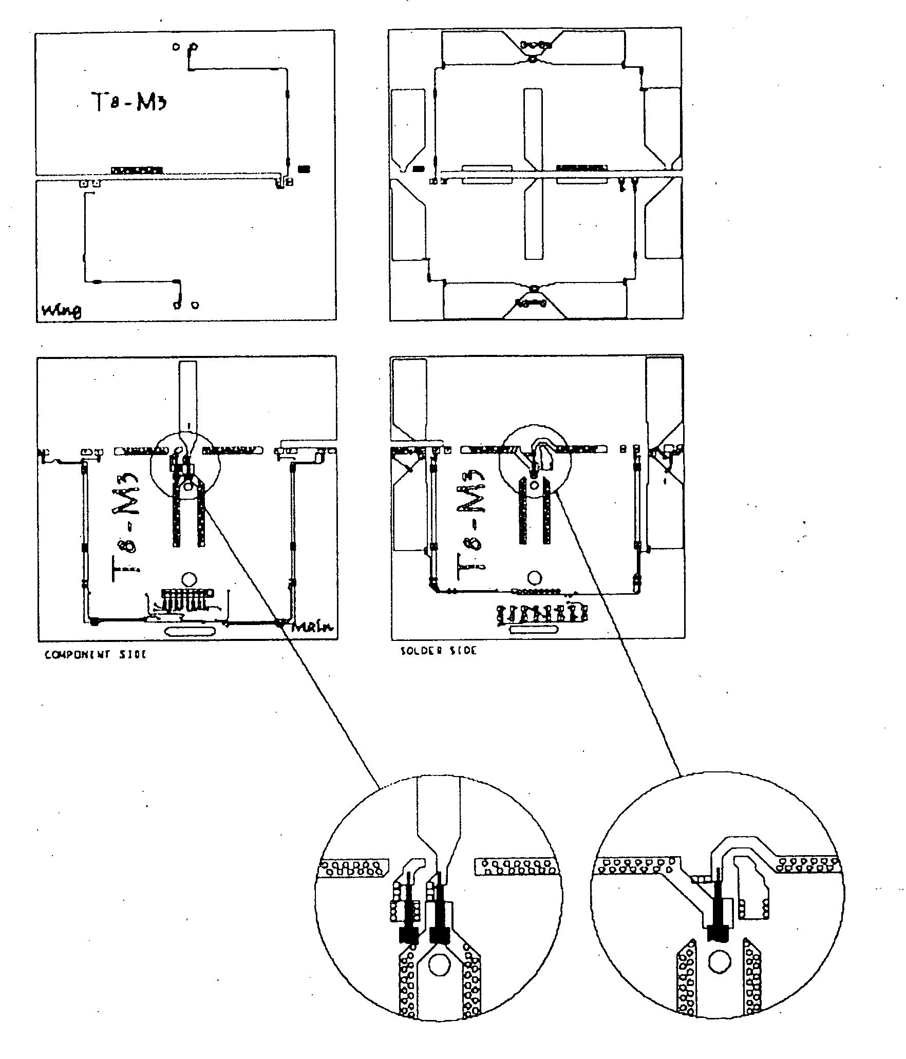
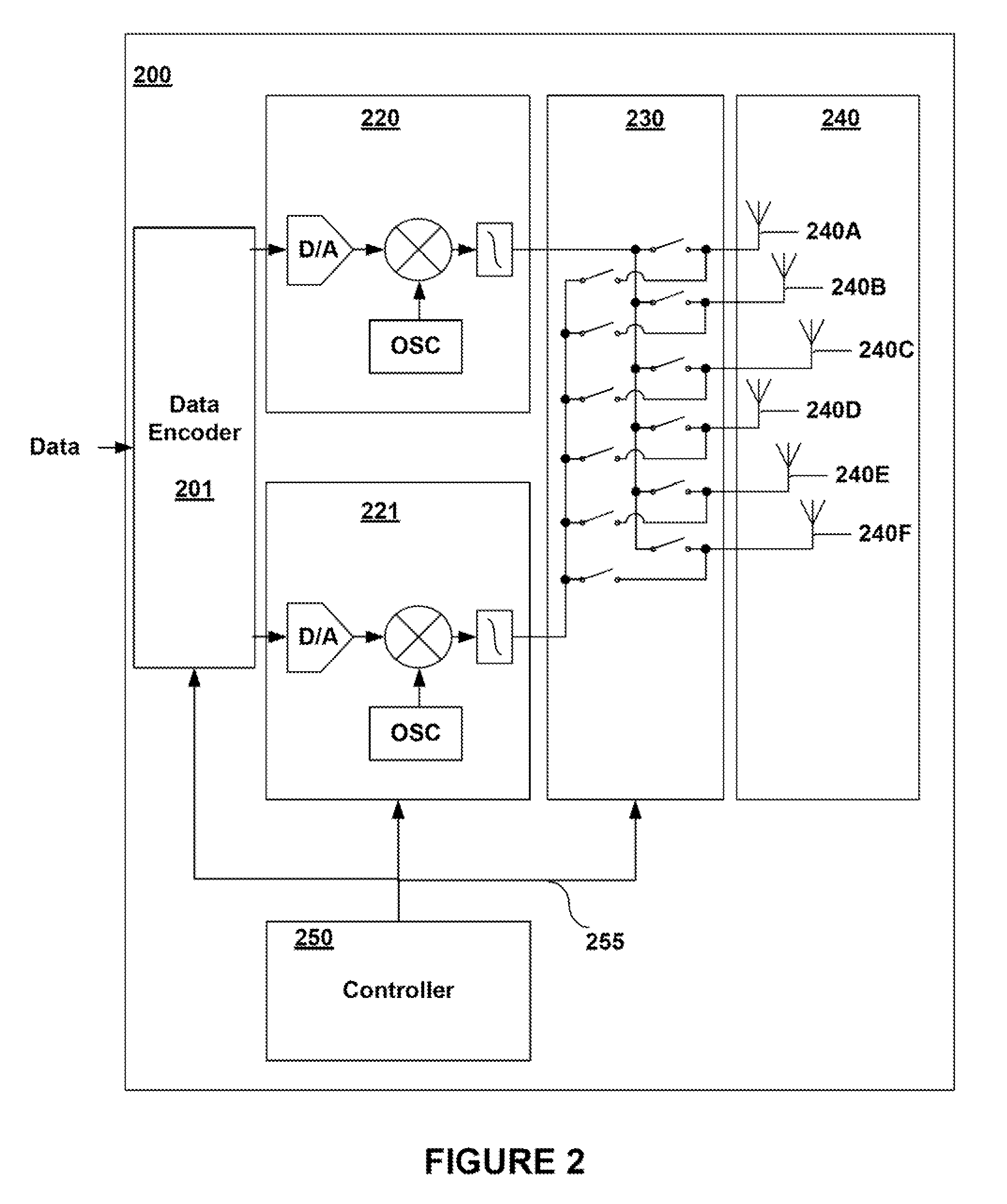
[0027]Embodiments of the present invention provide for high gain, multi-pattern MIMO antenna systems and antenna apparatus. These systems and apparatus may provide for multiple-polarization and omnidirectional coverage using multiple radios, which may be tuned to the same frequency. A MIMO antenna system or apparatus may be capable of generating a high-gain radiation pattern in a similar direction but having different polarizations. Each polarization may be communicatively coupled to a different radio. The antenna systems and apparatus may further be capable of generating high-gain patterns in different directions and that have different polarizations.

[0028]Embodiments may utilize one or more of three orthogonally located dipoles (and any related p-type, intrinsic, n-type (PIN) diodes) along the x-y-z-axes (as appropriate). The dipoles may be printed or fed and, in some embodiments, embedded in multilayer boards. Dipoles may be associated with reflector / director elements and the ant...


PUM


Abstract

High gain, multi-pattern multiple-input multiple-output (MIMO) antenna systems are disclosed. These systems provide for multiple-polarization and omnidirectional coverage using multiple radios, which may be tuned to the same frequency. The MIMO antenna systems may include multiple high-gain beams arranged (or capable of being arranged) to provide for omnidirectional coverage. These systems provide for increased data throughput and reduced interference without sacrificing the benefits related to size and manageability of an associated access point.

Description

CROSS-REFERENCE TO RELATED APPLICATIONS[0001]This application claims the priority benefit of U.S. provisional patent application No. 60 / 865,148 filed Nov. 9, 2006 and entitled “Multiple Input Multiple Output (MIMO) Antenna Configurations”; this application is also a continuation-in-part and claims the priority benefit of U.S. patent application Ser. No. 11 / 413,461 filed Apr. 28, 2006 and entitled “Coverage Antenna with Selectable Horizontal and Vertical Polarization Elements,” which claims the priority benefit of U.S. provisional patent application No. 60 / 694,101 filed Jun. 24, 2005. The disclosure of each of the aforementioned applications is incorporated herein by reference.[0002]This application is related to U.S. patent application Ser. No. 11 / 041,145 entitled “System and Method for a Minimized Antenna Apparatus with Selectable Elements”; U.S. patent application Ser. No. 11 / 022,080 entitled “Circuit Board having a Peripheral Antenna Apparatus with Selectable Antenna Elements”; U...

Claims


Application Information

Patent Timeline
Patent Type & Authority Applications(United States)
IPC IPC(8): H03C7/02
CPCH01Q3/242H01Q9/16H01Q13/10H01Q23/00H01Q21/24H01Q21/245H01Q21/205
Inventor SHTROM, VICTORBARON, BERNARD
Owner ARRIS ENTERPRISES LLC
Why Eureka
Try Eureka