Shaft Coupling Monitoring Apparatus

a technology of coupling monitoring and shaft coupling, which is applied in the direction of instruments, remote control toys, specific gravity measurement, etc., can solve the problems of shaft deflecting due to damage, and achieve the effect of increasing the detection accuracy of damag

Inactive Publication Date: 2008-06-12
JTEKT CORP
View PDF6 Cites 2 Cited by
  • Summary
  • Abstract
  • Description
  • Claims
  • Application Information

AI Technical Summary

Benefits of technology

[0016]The present inventors have found that the shaft coupling monitoring apparatus having the above constitution is adapted to determine whether or not the rolling contact surface sustains the damage such as flaking by operating the ultrasonic sensor to output the ultrasonic wave toward the rolling contact surface and to receive the ultrasonic wave reflected from the rolling contact surface. Specifically, in a case where the rolling contact surface is free from damage, the ultrasonic reflective wave from the rolling contact surface is received by the sensor, as hardly attenuated as compared with the ultrasonic outgoing wave. In a case where the rolling contact surface sustains some damage, on the other hand, the ultrasonic wave is diffused by the damage, so that the reflective wave reflected back to the sensor is seriously attenuated or that the sensor may not receive the reflective wave at all. The invention has been accomplished based on this finding and is adapted to immediately detect the occurrence of any damage on the rolling contact surface by detecting a variation of the ultrasonic reflective wave from the rolling contact surface. Since the ultrasonic sensor is disposed in the sh

Problems solved by technology

Only when the rolling contact surface sustains the d

Method used


Image

  • Shaft Coupling Monitoring Apparatus
  • Shaft Coupling Monitoring Apparatus
  • Shaft Coupling Monitoring Apparatus

Examples


embodiment 1

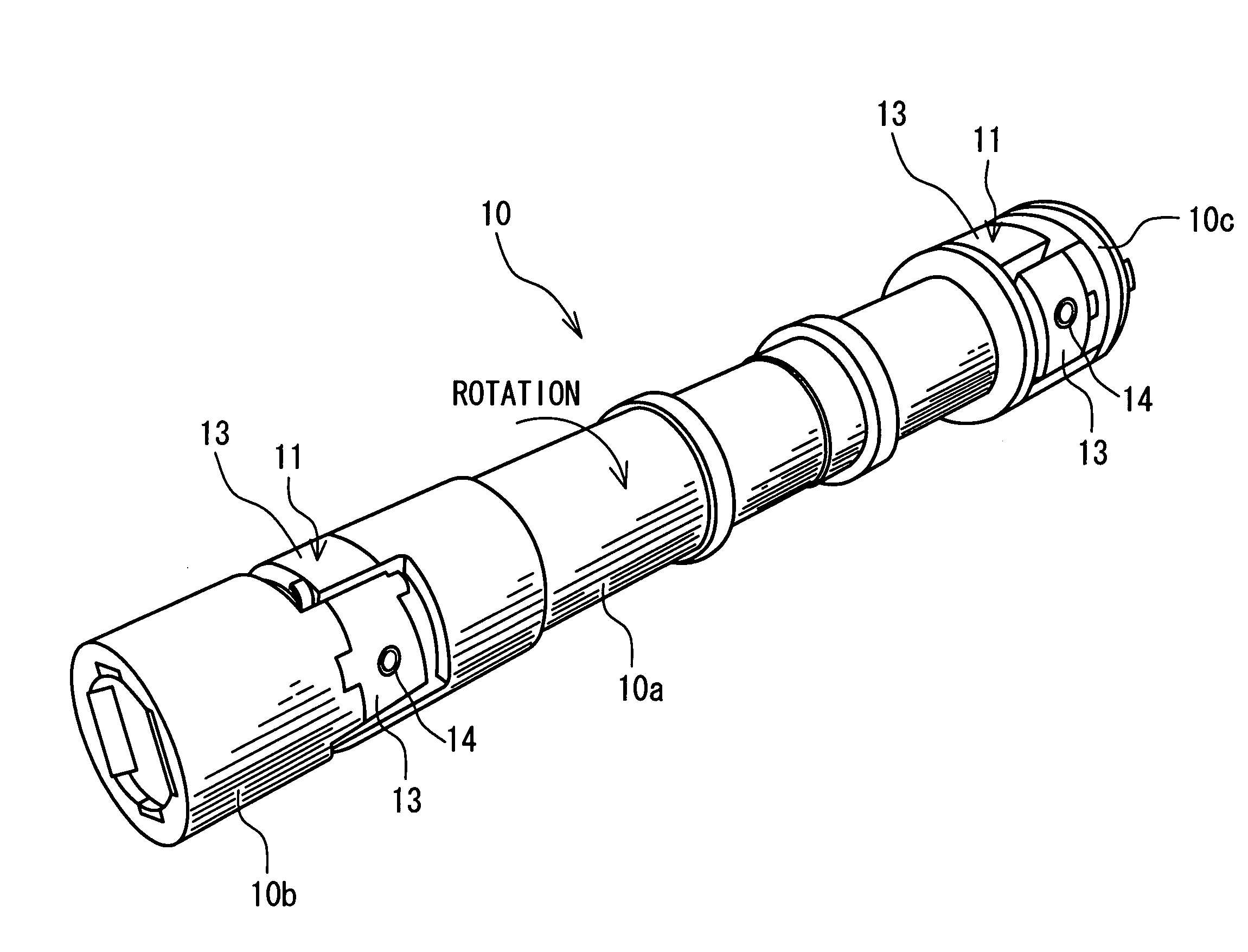
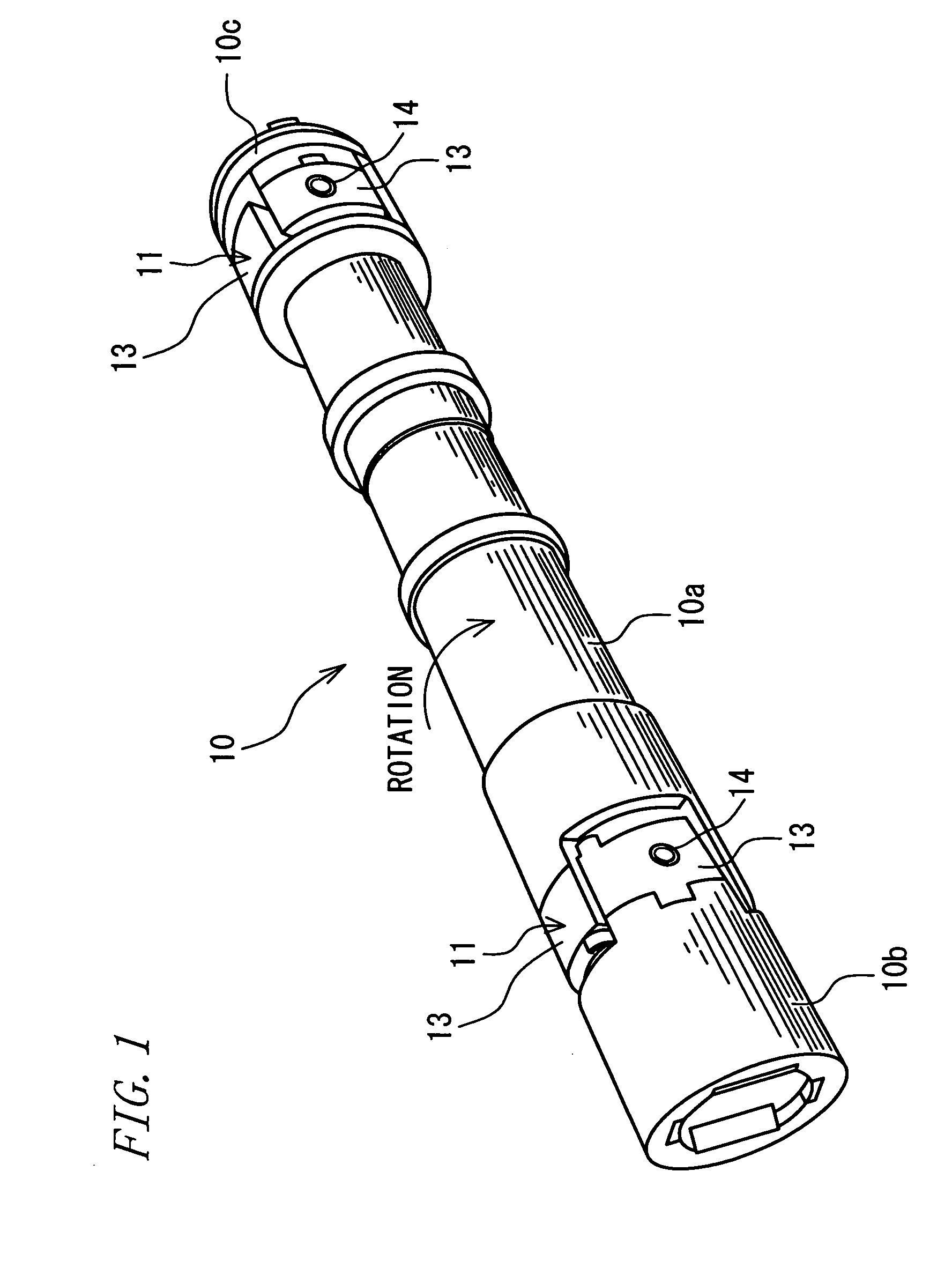
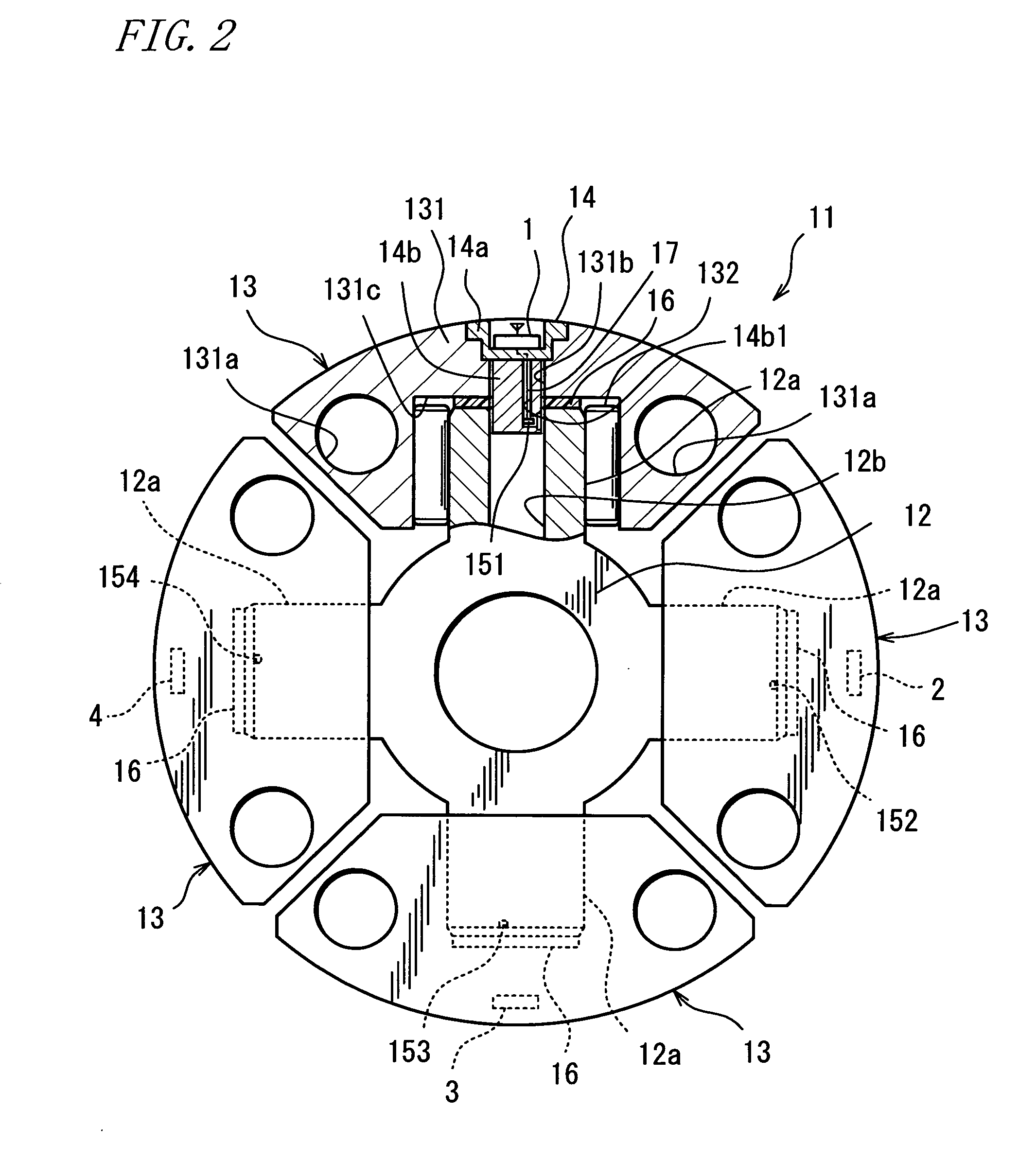
[0041]FIG. 1 is a perspective view showing a driving shaft for use in the rolling mill of steel manufacturers. FIG. 2 is a diagram (including a partial sectional view) showing an essential part of a shaft coupling monitoring apparatus according to one embodiment of the invention as viewed in an axial direction of the driving shaft. Referring to the figure, a driving shaft 10 has spider joints 11 mounted to places near the opposite ends thereof. The driving shaft 10 has one end and the other end thereof connected with an unillustrated drive motor and an unillustrated mill roll for steel rolling via the respective spider joints 11. Specifically, the driving shaft 10 includes an intermediate shaft portion (a first shaft portion) 10a interposed between the two spider joints 11, as well as a driving shaft portion (a second shaft portion) 10b and a driven shaft portion (a third shaft portion) 10c which are connected with the motor and the roll, respectively. One of the spider joints 11 in...

embodiment 2

[0078]FIG. 10 is a diagram (including a partial sectional view) showing an essential part of a shaft coupling monitoring apparatus according to another embodiment of the invention, as viewed in the axial direction of the driving shaft. Referring to the figure, Embodiment 2 principally differs from Embodiment 1 in that the displacement sensors 151 to 154 are replaced by ultrasonic sensors disposed in the respective shafts. The ultrasonic sensor is adapted to output an ultrasonic wave toward the rolling contact surface 12a1 of the shaft 12a and to receive the ultrasonic wave reflected from the rolling contact surface 12a1. Those components equivalent to those of Embodiment 1 are represented by the same reference characters, respectively, and the description thereof is dispensed with.

[0079]As shown in FIG. 10, the individual shafts 12a of the cross shaft 12 are provided with ultrasonic sensors 251, 252, 253, 254 in the respective holes 12b thereof. The ultrasonic sensors are included i...

embodiment 3

[0092]FIG. 13 is a group of diagrams showing an ultrasonic sensor of a shaft coupling monitoring apparatus according to another embodiment of the invention. Referring to the figure, Embodiment 3 principally differs from Embodiment 2 in that the fixing place of the ultrasonic sensor is shifted from the shaft side to the bearing-cup side. Those components equivalent to those of Embodiment 1 are represented by the same reference characters, respectively, and the description thereof is dispensed with.

[0093]Referring to FIG. 13, a sensor according to the embodiment is disposed in each shaft 12a as follows. The ultrasonic sensor 251, for example, is disposed in the hole 12b as mounted to a fixing member 14d attached to the support portion 14b (FIG. 10) of the lid 14 so as to be fixed to the bearing cup 13 via the lid 14. The ultrasonic sensor 251 of the embodiment is spaced away from the inside wall 12b1 of the hole 12b. In this state, the ultrasonic sensor outputs the ultrasonic outgoing...


PUM

PropertyMeasurementUnit
Distanceaaaaaaaaaa

Abstract

In a shaft coupling monitoring apparatus for monitoring a spider joint using outer peripheries of four shafts of a cross shaft as rolling contact surfaces, each of the shafts contains therein a sensor for detecting any damage on the rolling contact surface thereof. Even in a case where the spider joint is incorporated in a driving shaft such as of a rolling mill, the monitoring apparatus may provide high-accuracy and early detection of any damage such as flaking on the rolling contact surface defined on each of the shafts of the cross shaft.

Description

TECHNICAL FIELD[0001]The present invention relates to a shaft coupling monitoring apparatus for monitoring a spider joint incorporated in a driving shaft such as of a rolling mill.BACKGROUND ART[0002]In a steel rolling mill, for example, a spider joint is disposed at some place of a driving shaft connected between a mill roll and a drive motor in order to carry out a rolling process as allowing the mill roll to vertically move relative to a steel material being rolled.[0003]The above spider joint includes one which has the following constitution as disclosed in Japanese Unexamined Patent Publication No. H11(1999)-51073, for example. The spider joint is constituted such that a bearing cup is provided on each of four shafts of a cross shaft and rollers are rollably interposed between the cup and the shaft so as to utilize an outer periphery of the shaft as a rolling contact surface. This spider joint has the respective pairs of bearing cups on different lines connected to respective e...

Claims


Application Information

Patent Timeline
IPC IPC(8): F16D3/41F16C19/52
CPCB21B35/14F16D3/41G01N2291/2696G01N29/043G01N29/223F16D2300/18F16C19/52
Inventor KOMEYAMA, NOBUOSAKAMOTO, KENJI
Owner JTEKT CORP
Why Eureka
Try Eureka