Vascular Position Locating and/or Mapping Apparatus and Methods

a technology of positioning and mapping apparatus, applied in the field of prosthesis deployment, can solve the problems of increasing the risk of entanglement of these components, increasing the complexity of the procedure, and weakened walls of abnormally dilated vessels

Inactive Publication Date: 2008-06-12
MEDTRONIC VASCULAR INC
View PDF49 Cites 112 Cited by
  • Summary
  • Abstract
  • Description
  • Claims
  • Application Information

AI Technical Summary

Benefits of technology

[0020]In another embodiment according to the invention, a prosthesis delivery system comprises a stent-graft delivery catheter having a proximal end portion and a distal end portion; a first sensor coupled to the catheter distal end portion; a flexible member having a fixed end portion and a feeler end portion, the flexible member fixed end portion being secured to the catheter distal end portion; and a second signal sensor coupled to the flexible member feeler end portion and suspended thereby.
[0021]In another embodiment according to the invention, a prosthesis delivery system comprises a tubular prosthesis delivery sheath having a proximal end portion and a distal end portion; a tip member having a proximal end portion and a distal end portion, the tip member proximal end portion being releasably coupled to the sheath distal end portion; a first sensor coupled to the tip member; a flexible member having a fixed end portion and a feeler end portion, the flexible member fixed end portion being secured to the tip member; and a second sensor coupled to the flexible member and suspended thereby.
[0022]In another embodiment according to the invention, a stent-graft delivery system comprises a stent-graft delivery catheter having a proximal end portion and a distal end portion; a flexible member having a fixed end portion and a feeler end portion, the flexible member fixed end portion being secured to the catheter distal end portion; a first sensor coupled to one of the catheter distal end portion and the flexible member; a signal generator coupled to the other of the catheter distal end portion and the flexible member; and the one of the sensor and signal generator that is coupled to the flexible member being suspended thereby.
[0023]In another embodiment according to the invention, a stent-graft delivery system comprises a stent-graft delivery sheath having a proximal end portion and a distal end portion; a tip member having a proximal end portion and a distal end portion, the tip member being releasably coupled to the sheath distal end portion; a flexible member having a fixed end portion and a feeler end portion, the flexible member fixed end portion being secured to the tip member; a first sensor coupled to one of the tip member and the flexible member; a signal generator coupled to the other of the tip member and the flexible member; and the one of the sensor and signal generator that is coupled to the flexible member being suspended thereby and movable relative to the tip member.

Problems solved by technology

The abnormally dilated vessel has a wall that typically is weakened and susceptible to rupture.
Although the endovascular approach is much less invasive, and usually requires less recovery time and involves less risk of complication as compared to open surgery, there can be concerns with alignment of asymmetric features of various prostheses in relatively complex applications such as one involving branch vessels.
The procedure becomes more complicated when more than one branch vessel is treated.
One example is when an aortic abdominal aneurysm is to be treated and its proximal neck is diseased or damaged to the extent that it cannot support a reliable connection with a prosthesis.
Not only is there risk of entanglement of these components, the openings in an off the shelf prosthesis with preformed fenestrations may not properly align with the branch vessels due to differences in anatomy from one patient to another.
Prostheses having preformed custom located fenestrations or openings based on a patient's CAT scans also are not free from risk.
A custom designed prosthesis is constructed based on a surgeon's interpretation of the scan and still may not result in the desired anatomical fit.
When the vessel is reshaped, even a custom designed prosthesis may not properly align with the branch vessels.
Generally speaking, one challenge in prosthesis (e.g., stent graft) delivery / placement in the vicinity of one or more branch vessels is identifying and locating the position of branch vessels (e.g., arteries).
While physicians always try to use low dose rates during fluoroscopy, the duration of a procedure may be such that it results in a relatively high absorbed dose to the patient.

Method used


Image

  • Vascular Position Locating and/or Mapping Apparatus and Methods
  • Vascular Position Locating and/or Mapping Apparatus and Methods
  • Vascular Position Locating and/or Mapping Apparatus and Methods

Examples


Embodiment Construction

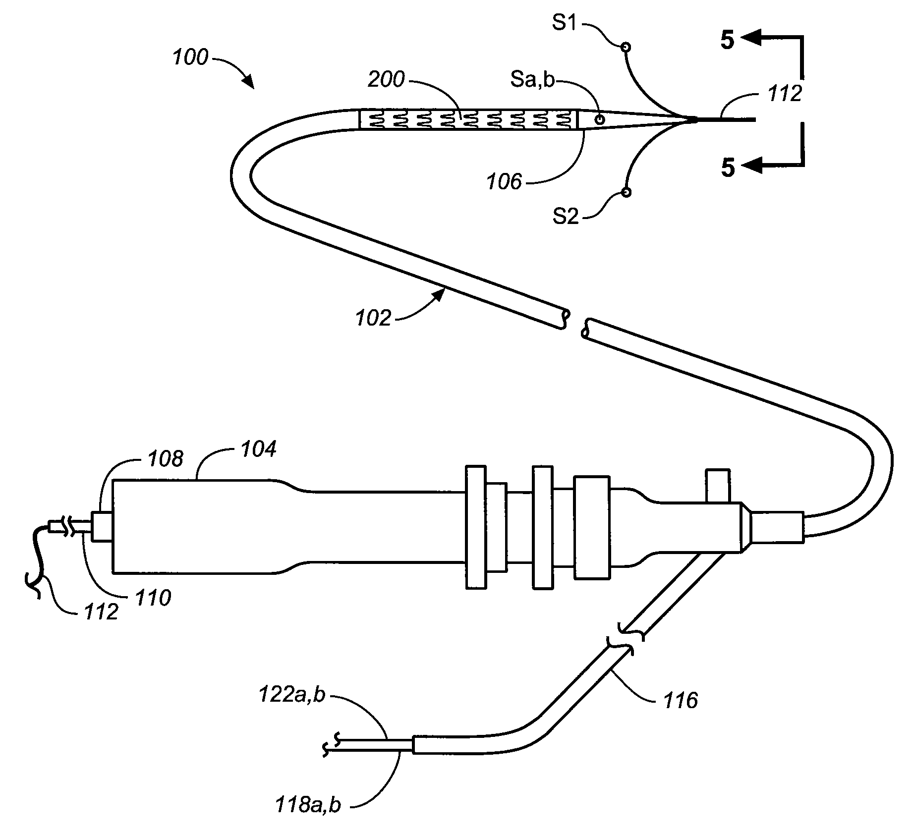
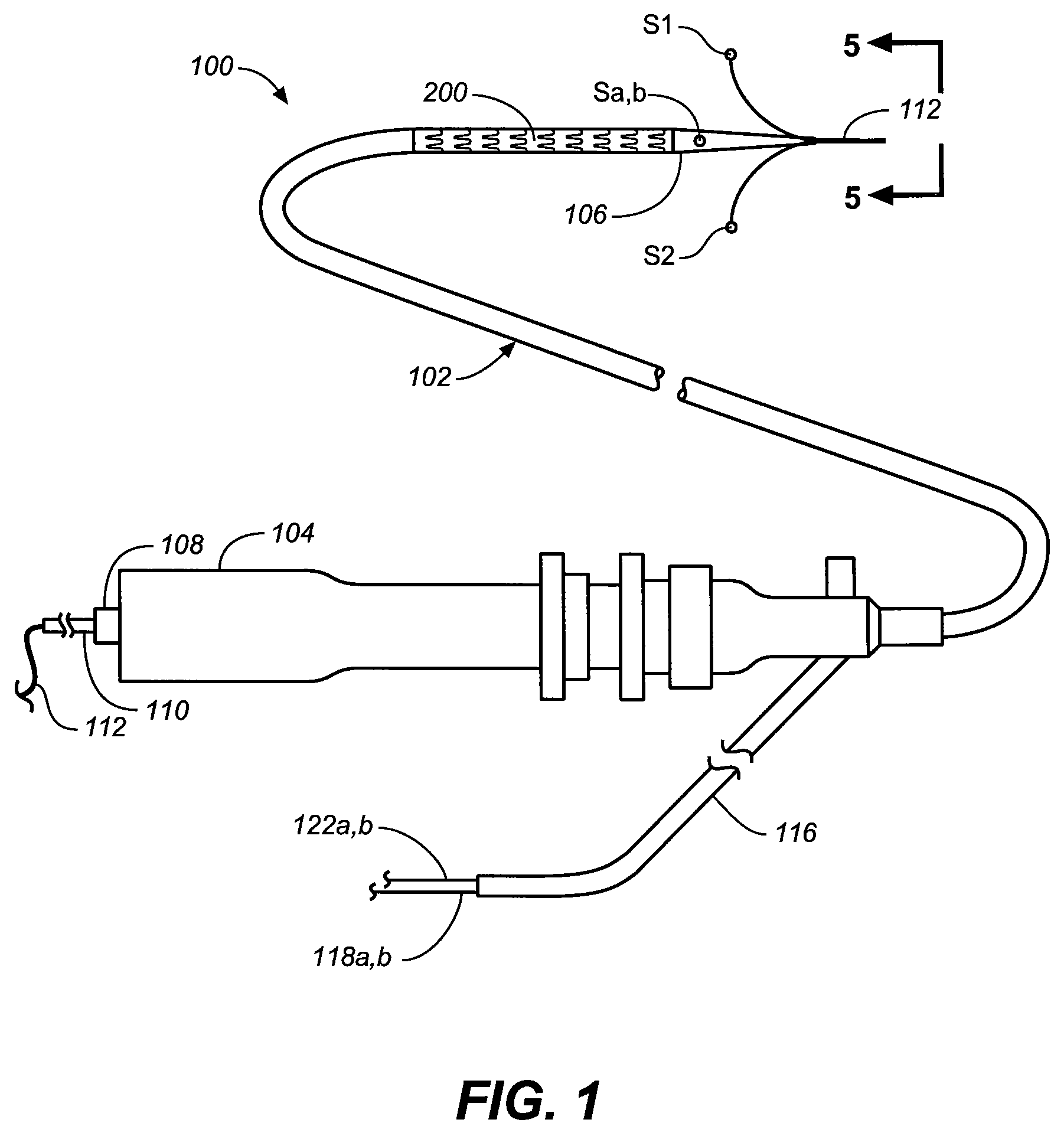
[0051]The following description will be made with reference to the drawings where when referring to the various figures, it should be understood that like numerals or characters indicate like elements.

[0052]Regarding proximal and distal positions, the proximal end of the prosthesis (e.g., stent-graft) is the end closest to the heart (by way of blood flow) whereas the distal end is the end farthest away from the heart during deployment. In contrast, the distal end of the catheter is usually identified as the end that is farthest from the operator, while the proximal end of the catheter is the end nearest the operator. Therefore, the prosthesis (e.g., stent-graft) and delivery system proximal and distal descriptions may be consistent or opposite to one another depending on prosthesis (e.g., stent-graft) location in relation to the catheter delivery path.

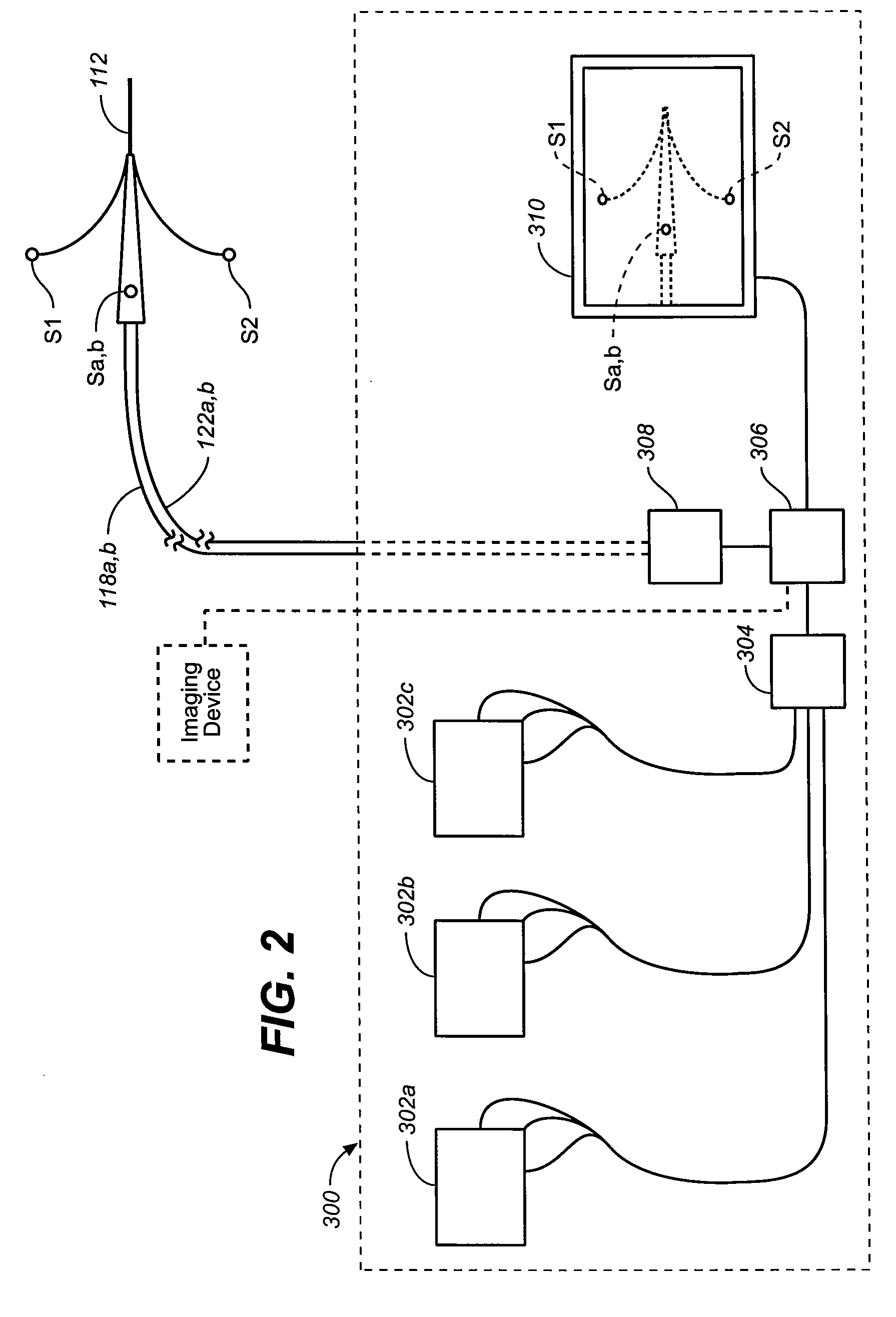
[0053]Embodiments according to the invention facilitate mapping of one or more branch lumens in a patient prior to stent-graft deploy...


PUM


Abstract

A branch vessel in a human patient is located or mapped using in vivo tracked field sensors where in one variation the sensor positions can be located by determining the positions of the sensors relative to a plurality of magnetic field sources of known location. This approach is used, for example, in locating the opening in a renal artery and positioning the proximal end of the AAA stent-graft adjacent to the opening. In another example, the sensors are tracked along the inner wall of an aneurysm and the acquired sensor location data processed to map the contour of the aneurysm to size a prostheses for spanning the aneurysm. The portions of the vessel adjacent the aneurysm also can be mapped. In a further embodiment, an in vivo sensor is positioned in a deployed prosthesis to create a reference for a prosthetic member having a sensor to track to during cannulation of the deployed prosthesis with the prosthetic member.

Description

CROSS-REFERENCE[0001]This application is a continuation-in-part application of Ser. No. 11 / 608,081, filed Dec. 7, 2006 and entitled Vascular Position Locating Apparatus and Methods, which application is incorporated herein by reference in its entirety and to which application we claim priority under 35 USC §120.FIELD OF THE INVENTION[0002]The invention relates to prosthesis deployment and more particularly to locating a branch passageway in a human body such as a branch artery prior to prosthesis deployment or locating a passageway in a prosthesis prior to in vivo cannulation thereof.BACKGROUND OF THE INVENTION[0003]Tubular prostheses such as stents, grafts, and stent-grafts (e.g., stents having an inner and / or outer covering comprising graft material and which may be referred to as covered stents) have been widely used in treating abnormalities in passageways in the human body. In vascular applications, these devices often are used to replace or bypass occluded, diseased or damaged...

Claims


Application Information

Patent Timeline
Patent Type & Authority Applications(United States)
IPC IPC(8): A61B5/05A61F2/06
CPCA61B5/06A61B5/6859A61B19/5244A61B2019/505A61B2019/508A61M2025/0166A61F2/07A61F2/954A61F2002/061A61F2002/067A61B2019/5251A61B5/062A61B34/20A61B2034/105A61B2034/108A61B2034/2051
Inventor DOLAN, MARKSIMON, DAVID
Owner MEDTRONIC VASCULAR INC
Why Eureka
Try Eureka