
Femoral Universal Nail

a universal nail and femoral nerve technology, applied in the field of femoral nerve nail, can solve the problems of increasing complexity of the muscular skeletal system of orthopaedic surgeons, high-energy trauma often caused, and difficult treatmen

Inactive Publication Date: 2008-06-12
KEBAISH ADEL
View PDF7 Cites 58 Cited by
  • Summary
  • Abstract
  • Description
  • Claims
  • Application Information

AI Technical Summary

Benefits of technology

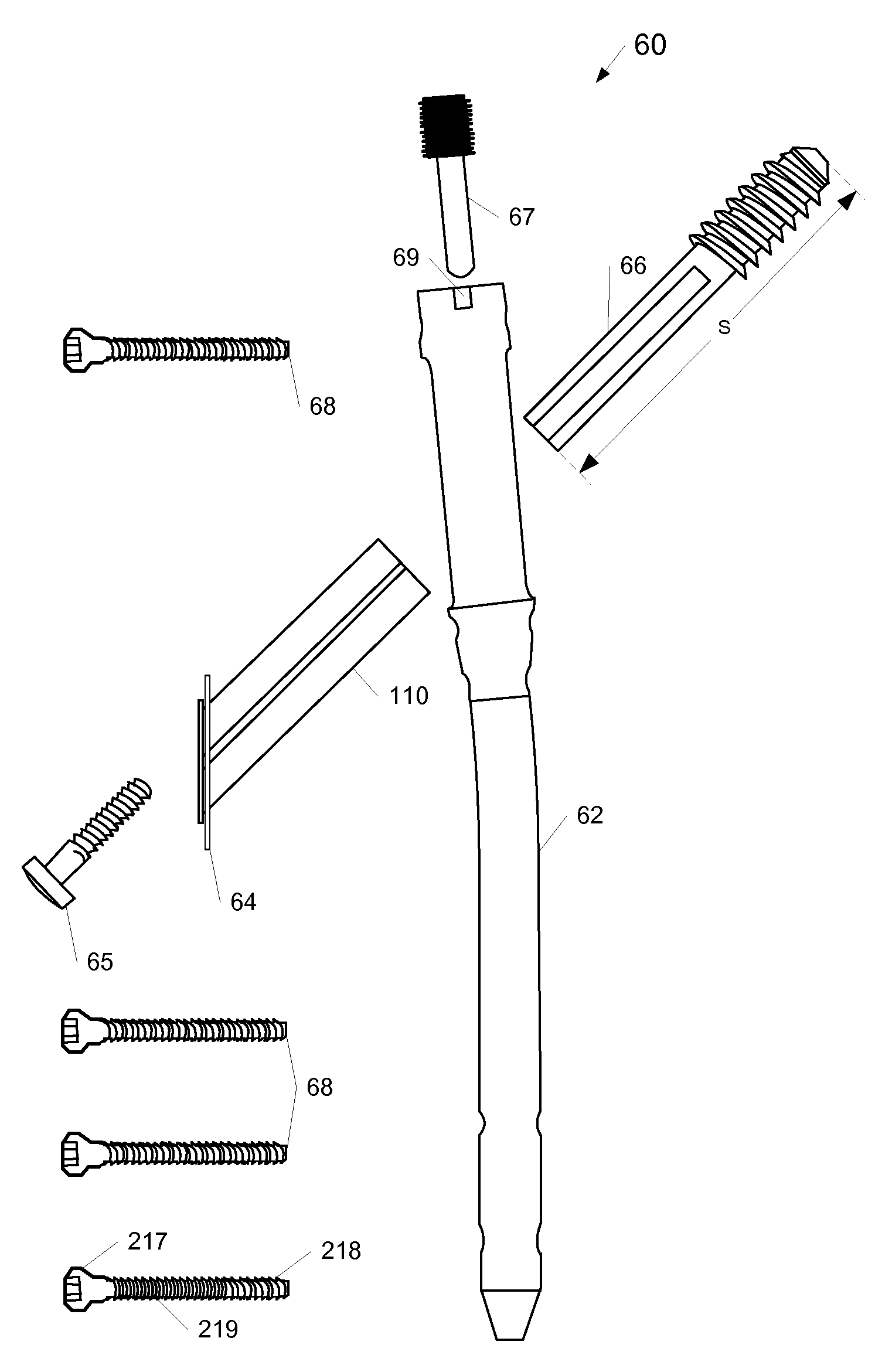
[0021]In an embodiment, an intramedullary nail for insertion in the intramedullary canal of a long bone includes a nail body having a leading end and a trailing end and a proximal diametral axis. The trailing end has an axial bore and an intersecting transverse slot. The transverse slot is adapted to pass a sleeve for a lag screw. The sleeve has a sleeve bore axis, and the transverse slot is adapted to provide alternative angles for the sleeve bore axis with respect to the proximal diametral axis. The nail includes a sleeve lock screw. The axial bore includes threads that are adapted to engage complementary threads of the sleeve lock screw. The axial bore is adapted to pass therethrough the sleeve lock screw to make contact with an upper surface of the sleeve when the sleeve is disposed within the transverse slot. A lower surface of the transverse slot and the sleeve lock screw restrict axial movement of the sleeve within the transverse slot and away from the leading end.

Problems solved by technology

Nowadays orthopedic trauma surgeons are faced with increasingly complex injuries to the muscular skeletal system, mainly the femur and the hip joint, due to increasingly high-energy trauma.
The high-energy trauma is often caused by construction injuries and automobile related crashes.
The treatment can be challenging and demanding.
However, a universal and versatile device for femoral fracture fixation has not been developed.
Although many femoral fixation devices have been invented and used over the years, none has been versatile enough to address the complex fractures, or combination of fractures.
Each of the devices was developed to address a limited scope of fractures and most of them inherently have a difficulty addressing the biomechanical instability of complex fracture combinations and especially so in osteoporotic bone.
In addition, each of these devices is inherently susceptible to failure if used beyond the limited scope of the fractures it was developed to treat.
This often compromises the safety and the stability of a device, increases operative time and blood loss, and may compromise immediate fracture stability.
Furthermore, the need for numerous devices often causes problems in determining how much of any particular device to stock.
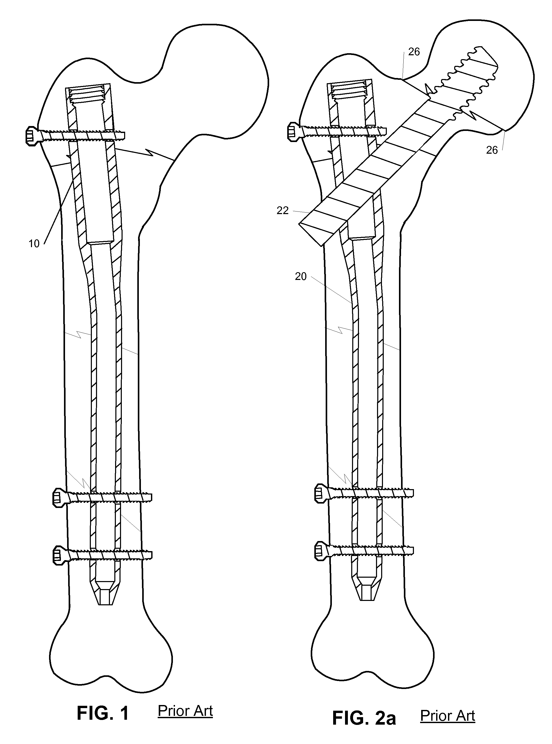
A fixed angle device has an inherent problem of not allowing compression and sliding at the fracture site, which often leads to many failures These devices have been abandoned except for a very limited set of fractures.
The dynamic hip screw has been found useful for treating stable hip fractures, but was never found to be suitable or indicated for the unstable hip fractures, especially the subtrochanteric fractures and reversed angle intertrochanteric fractures.
Moreover dynamic hip screws / plates do not address a combination of hip fracture and femoral shaft fracture, and certainly do not address complex, unstable femoral shaft fractures.
In addition, the foregoing two devices require an extensive surgical approach which may lead to increased bleeding and devitalization of bone fragment and soft tissue.
The IM nail will not address a subtrochanteric fracture or a combination of femoral neck / intertrochanteric fractures and even more so for supracondylar femur fractures, or a combination of the foregoing fractures.
However, this does not solve the problem of complex and combination fractures.
It is always difficult to place the proximal screws in the optimum location since they had to be introduced through a hole or two holes in the nail that provided limited flexibility with regards to angle of placement of the proximal screw(s) relative to the fracture geometry.
No IM nail is available to address the complex intercondylar and supracondylar distal femoral fractures.
Those usually are treated by a variety of plates—locking and non-locking—which often result in significant soft tissue stripping and devitalization of bone fragments.
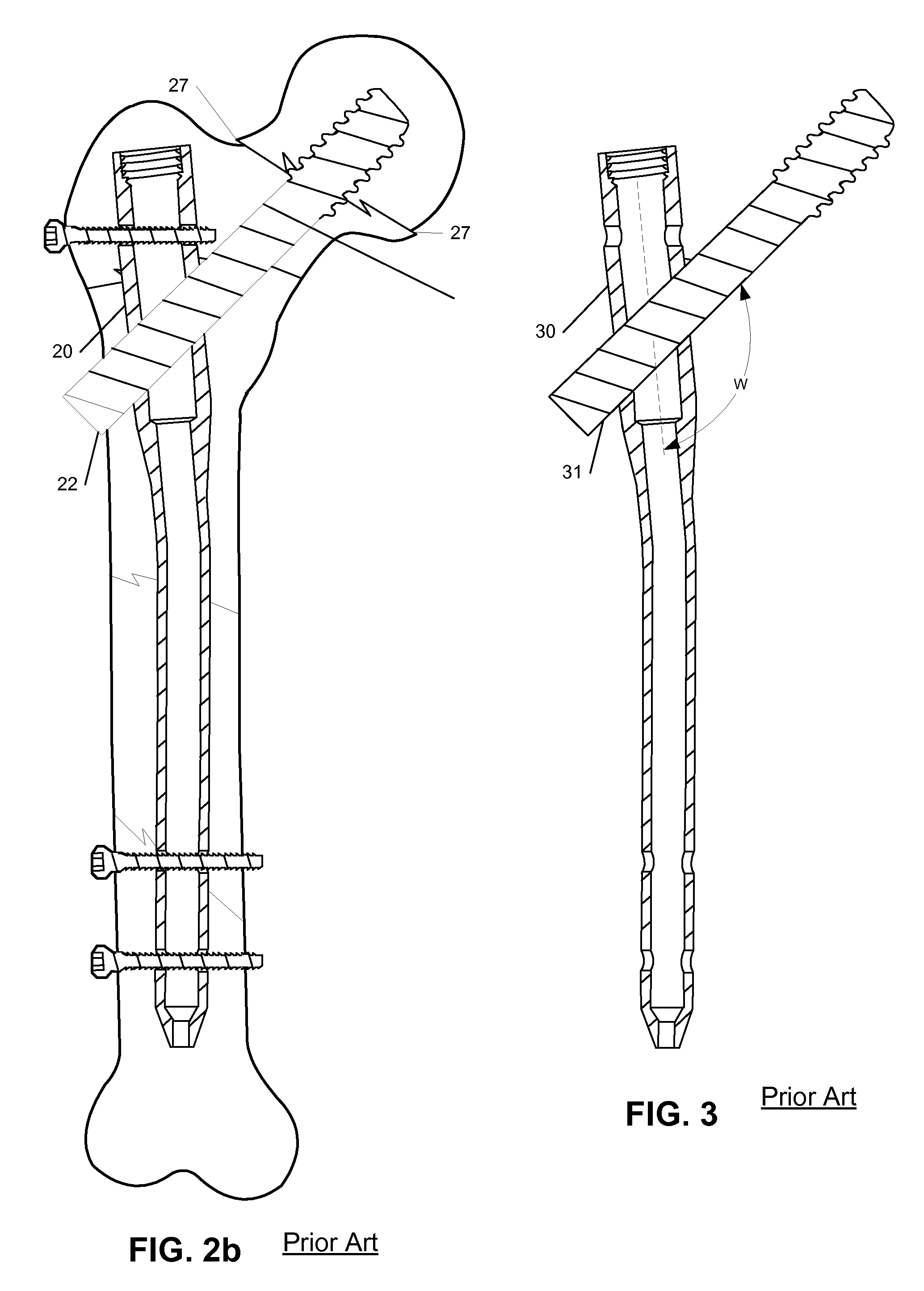
Gamma nails come with screw bores that have a fixed angle W, which may not be suitable for every fracture geometry and variable proximal hip anatomy.
Gamma nails do not provide for compression across the fracture site.
Mal-alignments could lead to failure of fixation, non-union, mal-union, or delayed union which may adversely affect the ultimate result of the surgery.
If it is locked it will control deformity due to rotation of the screw, but will not allow sliding.
If it is unlocked, it will allow sliding but will not control rotation of the screw.
It is not possible to predict definitively what type of mal-alignment, if any, will occur.
A dynamic hip screw does not treat a combination of intertrochanter fractures and fractures in the femoral shaft, including the subtrochanter region, due to the excessive forces across these fractures.
Using a dynamic hip screw in a first surgical operation complicates matters for a subsequent surgical operation which is supposed to treat new fractures in the shaft, subtrochanter, and intertrochanter regions.
Lack of load sharing may lead to delayed range of motion and weight bearing as well as frequent hardware failure, which may lead to mal-union, or non-union.
Dynamic hip screw will require an extensive surgical approach which may lead to soft tissue and bone devitalization.
As described above, current devices are limited in the number of cases they can treat causing problems with respect to stocking the appropriate types and number of devices.
The limited angles of insertion provided by current devices promote mal-alignment.

Method used


Image

  • Femoral Universal Nail
  • Femoral Universal Nail
  • Femoral Universal Nail

Examples


Embodiment Construction

[0080]According to the present invention, devices for treating fractures are described. Devices each of which allows a screw to be inserted across a fracture at one of several angles are also described. Furthermore, devices each of which allows a compressive force to be applied across a fracture at one of several angles are also described. In the following description, for purposes of explanation, numerous specific details are set forth in order to provide a thorough understanding of embodiments according to the present invention. It will be evident, however, to one of ordinary skill in the art that the present invention may be practiced in a variety contexts including treatment of femoral fractures without these specific details. In other instances, well-known operations, steps, functions and elements are not shown in order to avoid obscuring the description.

[0081]Parts of the description will be presented using terminology commonly employed by those skilled in the art to convey th...


PUM


Abstract

An intramedullary nail for insertion in the intramedullary canal of a long bone. The nail includes a nail body having a leading end, a trailing end, and a proximal diametral axis. The trailing end has an axial bore and an intersecting transverse slot. The transverse slot is adapted to pass a sleeve for a lag screw. The sleeve has a sleeve bore axis, and the transverse slot is adapted to provide alternative angles for the sleeve bore axis with respect to the proximal diametral axis. The nail includes a sleeve lock screw. The axial bore includes threads that are adapted to engage complementary threads of the sleeve lock screw. The axial bore is adapted to pass therethrough the sleeve lock screw to make contact with an upper surface of the sleeve when the sleeve is disposed within the transverse slot. A lower surface of the transverse slot and the sleeve lock screw restrict axial movement of the sleeve within the transverse slot and away from the leading end.

Description

BACKGROUND INFORMATION[0001]Nowadays orthopedic trauma surgeons are faced with increasingly complex injuries to the muscular skeletal system, mainly the femur and the hip joint, due to increasingly high-energy trauma. The high-energy trauma is often caused by construction injuries and automobile related crashes.[0002]The femur is the largest bone in the body. Fractures of the femur can be one, or a combination of the following: femoral neck fractures, complex hip fractures, subtrochanteric fractures, and femoral shaft fractures, including segmental fractures. Other fractures of some complexity often involve the lower part of the femur, otherwise known as the supracondylar fracture. Most often a combination of these fractures can exist in the same femur of the same multiple trauma patient. The treatment can be challenging and demanding.[0003]Over the years, treatment of femoral fractures has evolved due to progress and the development of orthopedic device technology. However, a unive...

Claims


Application Information

Patent Timeline
IPC IPC(8): A61B17/58
CPCA61B17/72A61B17/744A61B17/863A61B17/748A61B17/80A61B17/746
Inventor KEBAISH, ADEL
Owner KEBAISH ADEL
Learn More