Io adapter and data transferring method using the same

a technology of io adapters and data transfer methods, applied in the field of io adapters, can solve the problems of inability to guarantee the communication bandwidth required by the application program, inability to use individual capsule interfaces, and inability to control the bandwidth of individual capsule interfaces, so as to reduce congestion within the io interface, reduce the cost of lsi, and ensure data communication

Inactive Publication Date: 2008-06-12
HITACHI LTD
View PDF8 Cites 26 Cited by
  • Summary
  • Abstract
  • Description
  • Claims
  • Application Information

AI Technical Summary

Benefits of technology

[0019]The IO driver on the VMM unit can perform bandwidth control of each capsule interface so that the IO adapter hardware logic (circuitry) can be reduced to allow making the LSI chip surface area smaller so that the LSI cost can be lowered.
[0020]Moreover bandwidth control can be performed at a finely distributed level for each capsule interface so that congestion within the IO interface can be reduced and stable data communication achieved.

Problems solved by technology

However the present inventors found that the capsule interface technology of the related art possesses the following problems.
Namely the related art had the problem that when applying capsule interface technology by bandwidth control technology using DMA transfer, that bandwidth control was only applied in DMA engine units and so could not be used for individual capsule interfaces.
The related art therefore had the problem that the communication bandwidth required by the application program could not be guaranteed even if a capsule interface was applied to each application program.

Method used


Image

  • Io adapter and data transferring method using the same
  • Io adapter and data transferring method using the same
  • Io adapter and data transferring method using the same

Examples


first embodiment

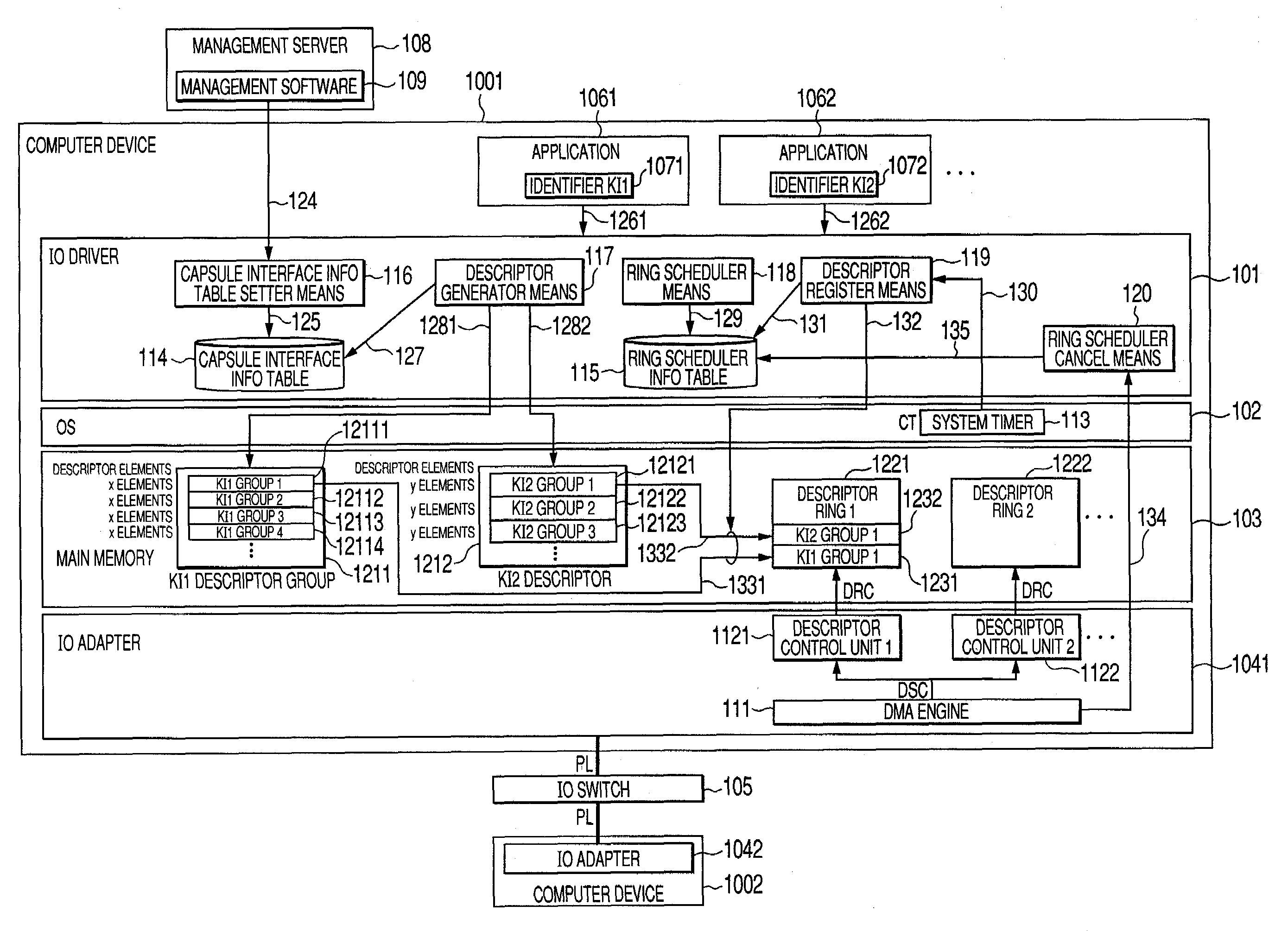
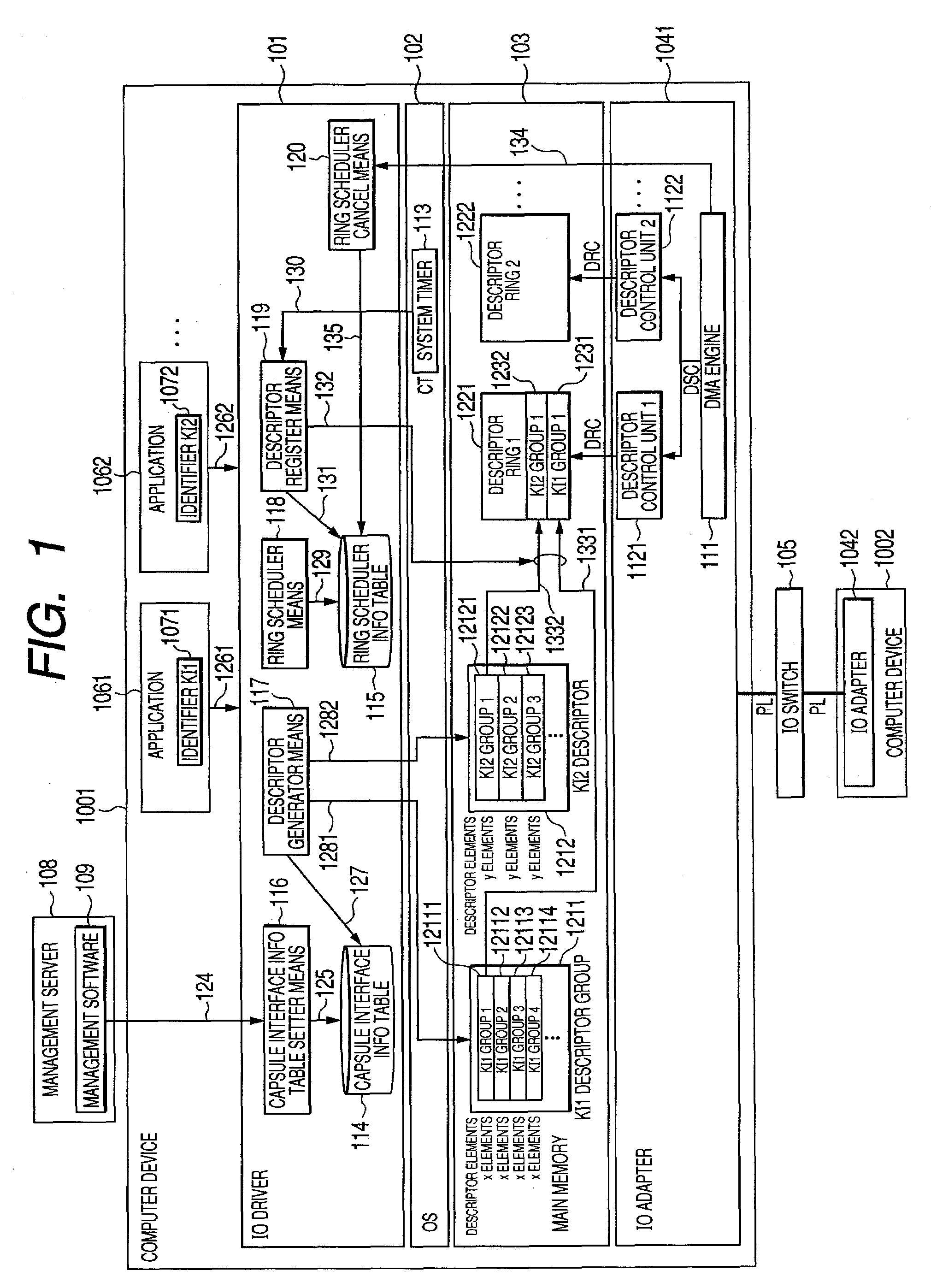
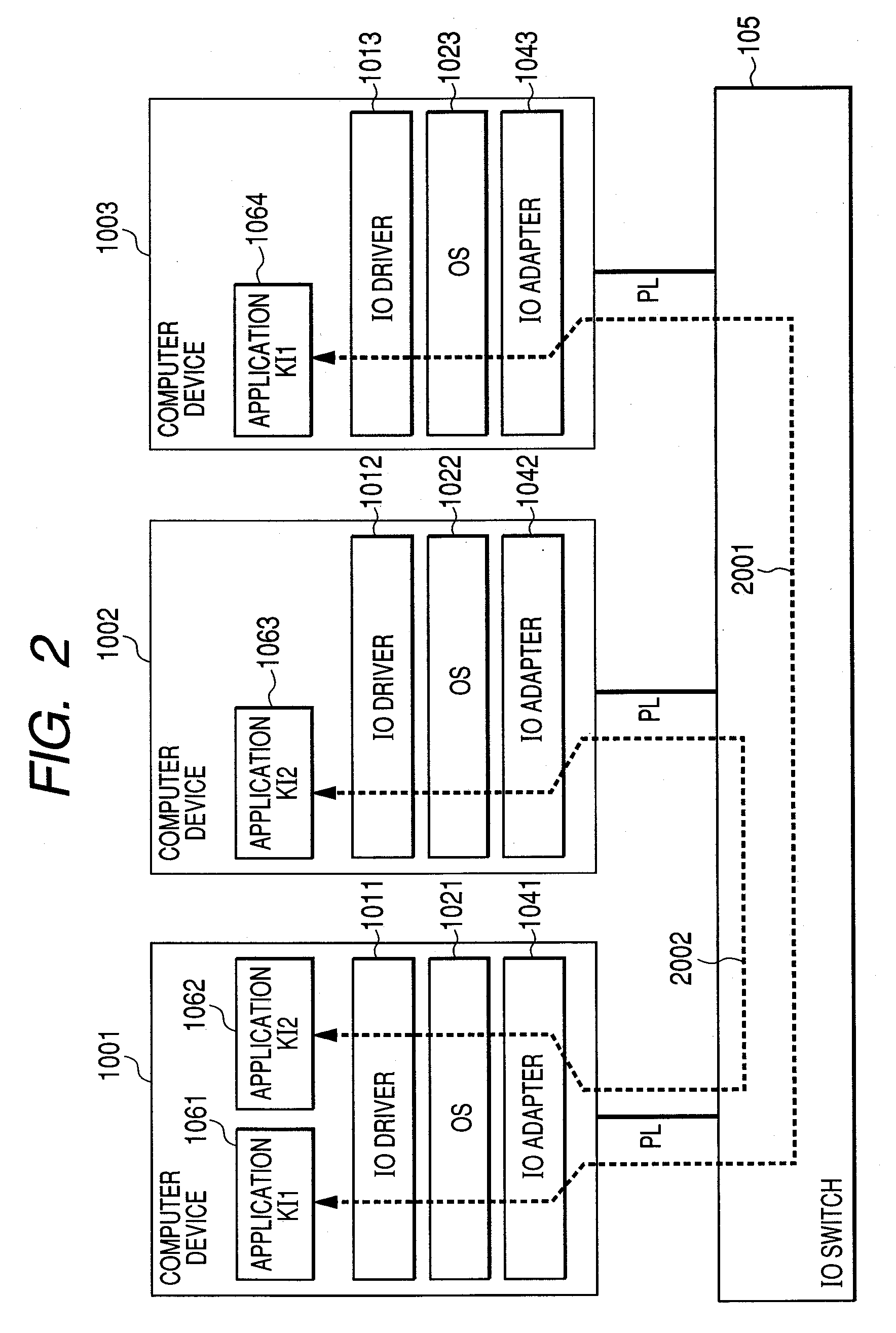
[0046]FIG. 1 is a block diagram of the IO driver and the IO adapter of the first embodiment of this invention. FIG. 2 is a drawing showing one example of data communication between computer devices containing the IO adapter of the first embodiment. In a typical structure for data communication using the IO adapter of this invention as shown in FIG. 2, the IO adapters 1041, 1042, 1043 are respectively mounted in the computer devices 1001, 1002, 1003; and the IO drivers 1011, 1012, 1013 serving as the drivers for the IO adapters 1041, 1042, 1043 operated on the operation systems (OS) 1021, 1022, and 1023. The computer devices 1001, 1002, 1003 are respectively connected via the physical wiring PL to the IO switch 105 and carry out mutual data communication. When the application programs 1061, 1062, 1063, and 1064 operating on the computer devices are carrying out data communication by using the IO adapters 1041, 1042, 1043, then the optional protocol is encapsulated into the protocol f...

second embodiment

[0063]The structure of the IO adapter of the second embodiment of this invention is described next while referring to FIG. 13. FIG. 13 is a drawing for describing an example of the capsule interface information table of the second embodiment. The IO adapter of the second embodiment differs from the IO adapter of the first embodiment in the capsule interface information table 114 section. The following description covers the points differing from the first embodiment.

[0064]In the second embodiment as shown in FIG. 13, priority information K1301 has been added to the capsule interface information table 114. This priority (level) information is utilized to control the priority levels between the capsule interfaces KI1, KI2. This priority control method for example, changes the descriptor rings 1221, 1222 and so on, for each of the priority level information and adds priority levels to the arbitration method used by the descriptor control units 1121, 1122 of DMA engine 111. However, the...

third embodiment

[0065]The structure of the IO adapter of the third embodiment of this invention is described next while referring to FIG. 14 and FIG. 15. FIG. 14 is a block diagram of the IO adapter and the IO driver of the third embodiment. FIG. 15 is a flow chart of the data transfer method using the capsule interface during changing of bandwidth information by the IO adapter in the third embodiment. The IO adapter of the third embodiment differs from the IO adapter of the first embodiment shown in FIG. 1 in that a section of the IO driver is different. Namely, a bandwidth changer means 1400 has been added to the IO driver of the third embodiment as shown in FIG. 14.

[0066]The operation in the third embodiment during bandwidth information changing, when the application programs 1071, 1072 are transferring data by using the capsule interfaces KI1, KI2 is described next while referring to FIG. 15. The management software 109 makes a request via the IO driver 101 per the management interface 1401 for...


PUM


Abstract

An IO adapter for guaranteeing the data transfer bandwidth on each capsule interface when multiple capsule interfaces jointly share the DMA engine of the IO adapter. An IO driver containing a capsule interface information table including bandwidth information and for setting the forming status of a pair of capsule interfaces and, during data transfer subdivides the descriptors for the capsule interfaces into multiple groups for each data buffer size satisfying the preset bandwidth information and, copies one group at each fixed sample time set by the descriptor registration means, into the descriptor ring and performs DMA transfer. To control this copy information, the IO driver contains a ring scheduler information table for managing the number of descriptor entries for the capsule interface cycle time and, a ring scheduler cancel means for renewing the entries in the ring scheduler information table each time one transmission of the descriptor group ends.

Description

CLAIM OF PRIORITY[0001]The present application claims priority from Japanese application JP 2006-328934 filed on Dec. 6, 2006 and JP 2007-146429 filed on Jun. 1, 2007, the contents of which are hereby incorporated by reference into this application.FIELD OF THE INVENTION[0002]This invention relates to data transfer technology for I / O adapters mounted in information platform equipment typified by server devices, storage devices and network switching devices, and relates in particular to technology effective for bandwidth control of multiple capsule interfaces in capsule interface technology for carrying out data communication between devices via optional capsule protocols.BACKGROUND OF THE INVENTION[0003]IT systems on the Internet mutually connect systems made up of server devices, storage devices and client terminals, to perform data communication using protocols of diverse types. Typical protocols include the Ethernet, fiber channels and InfiniBand, etc. In this type of data commun...

Claims


Application Information

Patent Timeline
Patent Type & Authority Applications(United States)
IPC IPC(8): G06F13/28
CPCG06F9/5011
Inventor BABA, TAKASHIGEYASUDA, YOSHIKOOKITSU, JUN
Owner HITACHI LTD
Why Eureka
Try Eureka