Machine component configuration for enhanced press fit and press fit coupling method

Active Publication Date: 2008-06-19
CATERPILLAR INC
View PDF22 Cites 26 Cited by
  • Summary
  • Abstract
  • Description
  • Claims
  • Application Information

AI Technical Summary

Benefits of technology

[0007]In one aspect, the present disclosure provides a machine having a first machine component with a bore therein, and a second machine component having a first end, a second end and a length extending between the first and second ends. One of the ends of the second machine component is retained within the bore by a press fit. The second machine component further includes a non-directional surface finish disposed along a portion of its length within the bore which is configured via the press fit to form a fluid seal with the bore, and a directional surface finish disposed along a different portion of its length within the bore which is configured via the press fit to inhibit removal of the end from the bore.
[0008]In another aspect, the present disclosure provides a method of coupling together machine components, including press fitting an end of a first machine component into a bore in a second, different machine component. Press fitting the end of the first machine component into a bore includes forming a fluid seal between the first machine component and the second machine component via a non-directional surface finish disposed along a portion of a length of the first machine component which is positioned within the bore. Press fitting the end of

Problems solved by technology

Increasing the relative interference between the components can in some instances increase the “strength” of the press fit, however, there are limits to the practicability of this approach.
In particular, too much interference between press fit components can result in galling of the materials' surfaces as they are pressed together, sometimes compromising the integrity of the joint, and certainly preventing re-assembly if the components are ever de-coupled.
Track-type machines such as those used in various earth moving, construction, mining and similar industries inherently operate in rugged environments, which can subject press fit joints in the machines to forces sufficient to affect their integrity.
In extreme cases, movement of one of the parts r

Method used


Image

  • Machine component configuration for enhanced press fit and press fit coupling method
  • Machine component configuration for enhanced press fit and press fit coupling method
  • Machine component configuration for enhanced press fit and press fit coupling method

Examples


Embodiment Construction

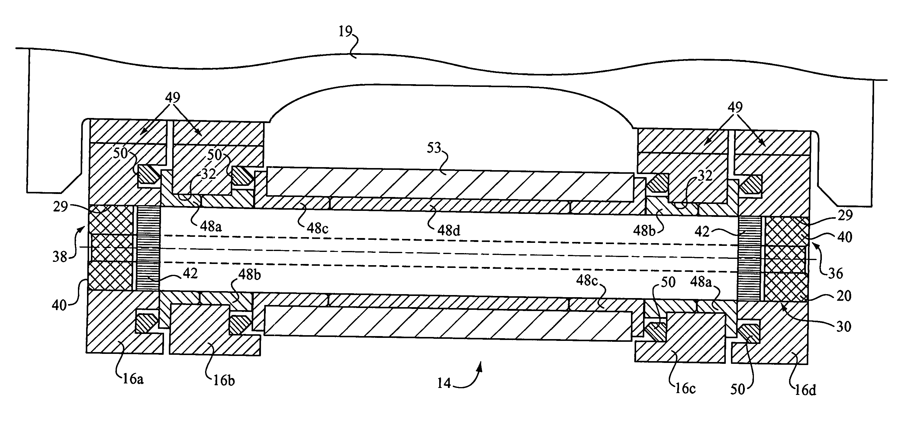
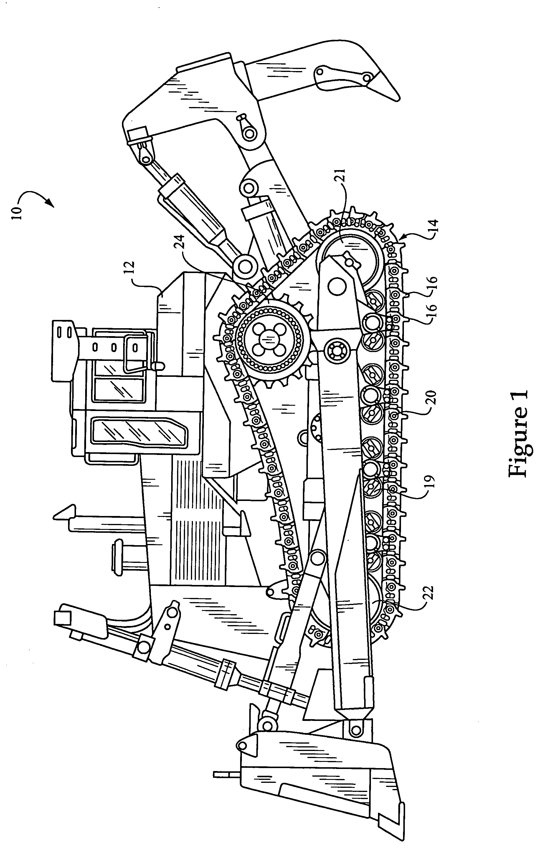
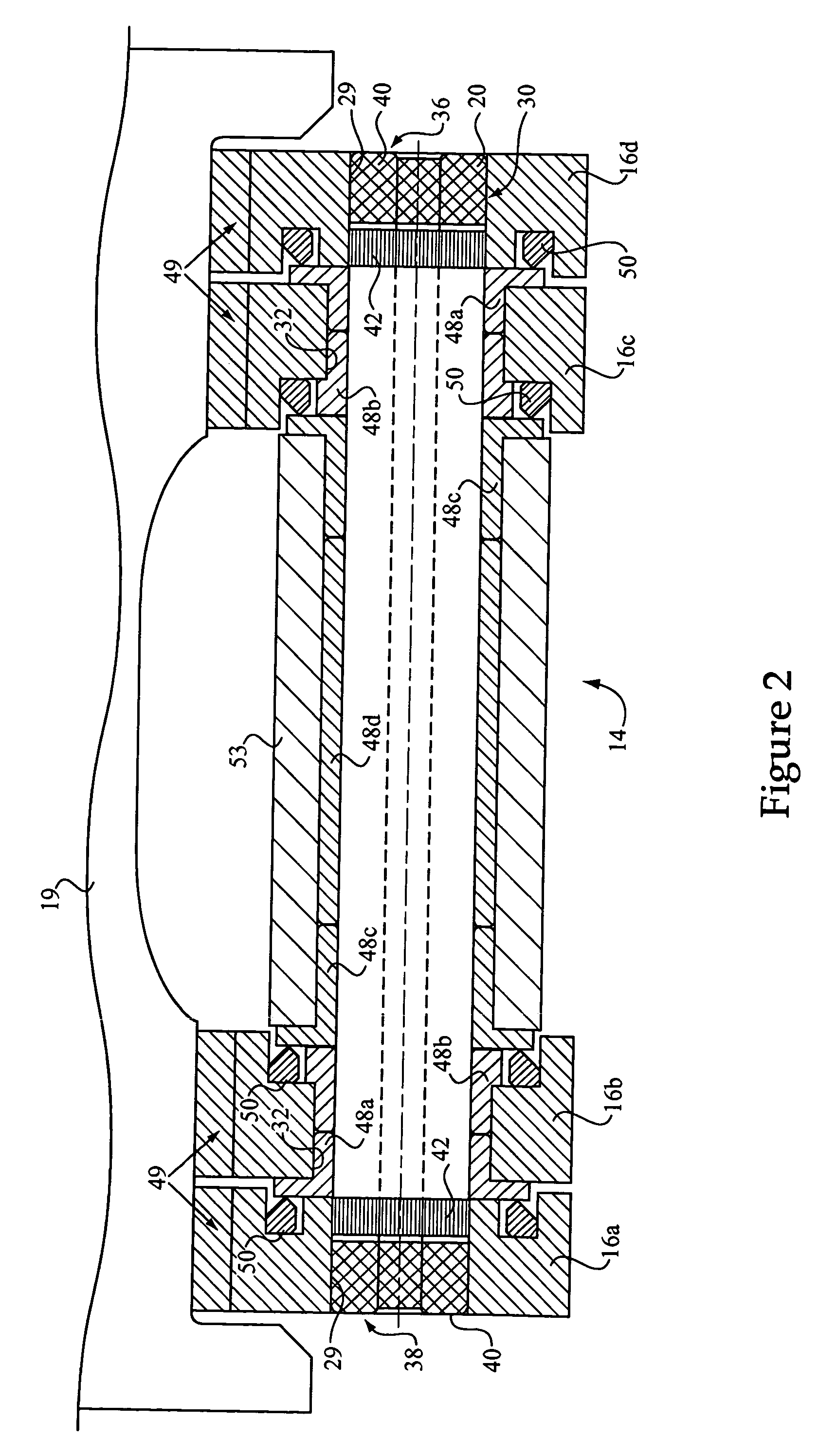
[0015]Referring to FIG. 1, there is shown a machine 10 according to the present disclosure. Machine 10 is shown in the context of a track-type machine having a frame 12 with a first track 14 disposed at a first side of frame 12, and a second track (not shown) disposed on an opposite side of frame 12. It will be understood by those skilled in the art that the respective tracks of machine 10 will typically consist of identical tracks disposed on opposite sides of frame 12 and configured to engage the ground for propelling machine 10 across a work surface. Track 14 will typically extend in an endless loop about a plurality of rolling elements, including a front idler 22, a back idler 21 and a drive roller or sprocket 24, as well as a plurality of smaller track rollers 19 disposed between front and back idlers 22 and 21. Track 14 will also typically consist of a plurality of coupled together links 16. A plurality of pins 20 are provided which may couple together at least two of the trac...


PUM

PropertyMeasurementUnit
Angleaaaaaaaaaa
Angleaaaaaaaaaa
Angleaaaaaaaaaa

Abstract

A machine is provided including a frame and at least one track, such as first and second ground engaging tracks, coupled with the frame. A plurality of pins are provided which each couple together at least two of the links of the tracks and include an outer diameter, a first end and a second end. The first and second ends of the pin may be press fit in first and second bores of first and second links of the tracks, respectively. A non-directional surface finish along a first portion of the length of the pin within the first bore forms a fluid seal with the first bore, whereas a directional surface finish along a different portion of the length of the pin within the first bore inhibits removal of the first end of the pin from the first bore. A method of coupling together machine components via an enhanced press fit is further provided, utilizing a pin having a first surface finish configured to form a fluid seal with a bore of a machine component, and a second surface finish configured to inhibit removal of the pin from the bore.

Description

TECHNICAL FIELD[0001]The present disclosure relates generally to machines having components coupled together via press fits, and relates more particularly to a machine component and method wherein a press fit is enhanced via specialized surface finishes of press fit components.BACKGROUND[0002]Press fits are used across virtually all industries to couple together machine components. A component having a cylindrical outer diameter is typically pressed into a bore in a second component which includes a cylindrical inner diameter having an interference fit with the outer diameter of the first component. Press fitting the components creates a joint coupling them together. In many instances, the press fit between the components is intended to be permanent, and relatively strong forces are required to de-couple the components. Increasing the relative interference between the components can in some instances increase the “strength” of the press fit, however, there are limits to the practica...

Claims


Application Information

Patent Timeline
IPC IPC(8): B23P19/04
CPCB21K25/00B21L9/065B23P11/00B62D55/0887Y10T29/53796B62D55/21F16D1/0858F16D2300/10B62D55/14
Inventor LIVESAY, RICHARD E.
Owner CATERPILLAR INC
Why Eureka
Try Eureka