
Positioned based motor tuning for a guillotine cutter mechanism

a guillotine cutter and positioned-based technology, applied in the direction of electric controllers, instruments, ignition automatic control, etc., can solve the problems of difficult, if not impossible, in determining the tuning coefficient that provides satisfactory or optimized motion control performance, so as to improve the tuning of servo motors, reduce lag or overshoot, and reduce the effect of lag

Active Publication Date: 2008-06-19
DMT SOLUTIONS GLOBAL CORP
View PDF8 Cites 8 Cited by
  • Summary
  • Abstract
  • Description
  • Claims
  • Application Information

AI Technical Summary

Benefits of technology

[0011]The present invention provides a method for improved tuning of servo motors used to drive guillotine cutters. Rather than providing a single tuning coefficient to the motor, the tuning coefficient is continuously varied during the blade's cutting cycle. The novel method for selecting the varying tuning coefficients allows rapid and precise cutting and minimizes lag or overshooting.

Problems solved by technology

For mechanisms that have inertial and friction loads that are not constant, determination of tuning coefficients that provide satisfactory or optimized motion control performance can be difficult, if not impossible to achieve.

Method used


Image

  • Positioned based motor tuning for a guillotine cutter mechanism
  • Positioned based motor tuning for a guillotine cutter mechanism
  • Positioned based motor tuning for a guillotine cutter mechanism

Examples


Embodiment Construction

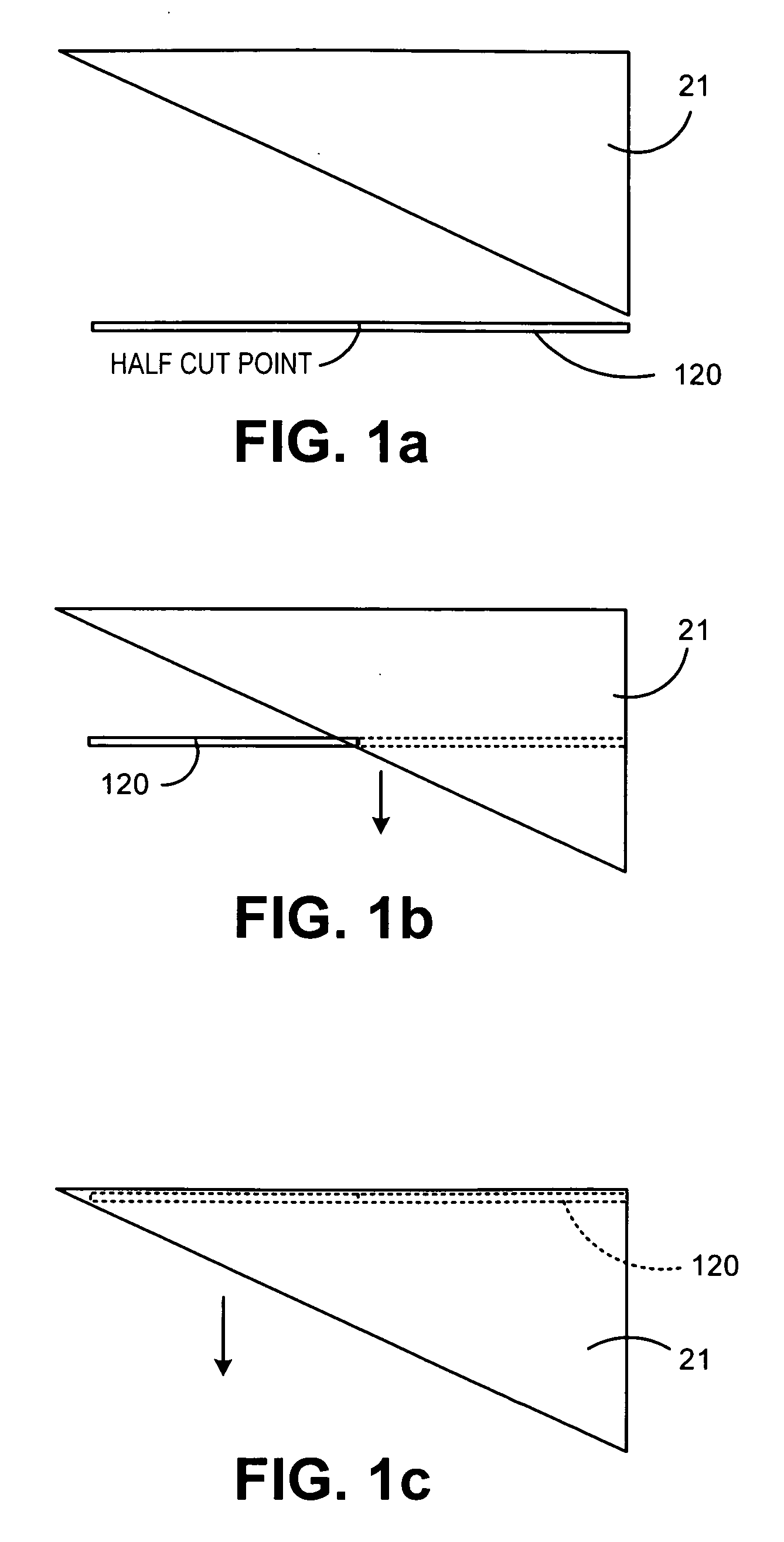
[0023]FIGS. 1a-1c depict the guillotine cutter 21 through a downward cutting motion, starting at a beginning position in 1a, to a finished cut position in 1c. Guillotine cutter blade 21 preferably has an edge that is vertically inclined at an angle above the path of web 120. As the blade 21 is lowered (FIG. 1b) the blade 21 edge comes into contact with the web and cuts across its width (from right to left in FIGS. 1a-c). In FIG. 1c, the blade has reached its bottom position, and the whole width of the web 120 has been cut. In an alternative scenario, blade 21 can be stopped at the position shown in FIG. 1b, and only the right half of the web has been cut. This technique is used when the web 120 is comprised of side-by-side sets of sheets, and where only one of the sheets belongs to the mailpiece that is currently being processed. The other half of the web 120 can be cut when the system is ready to start processing the collection of sheets for the next mailpiece.

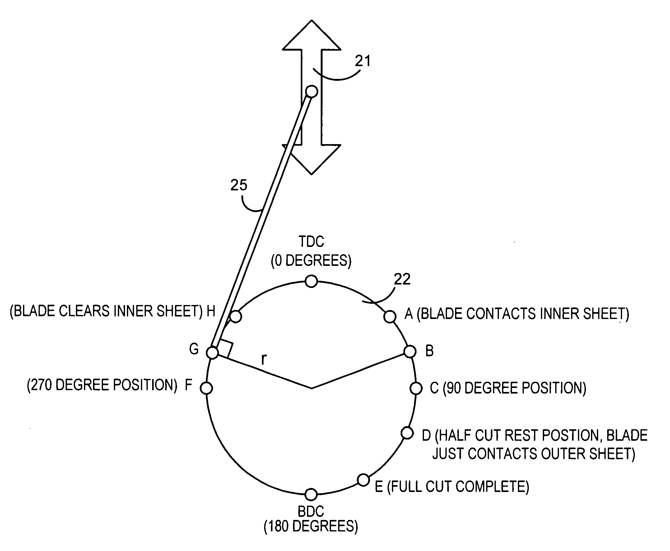
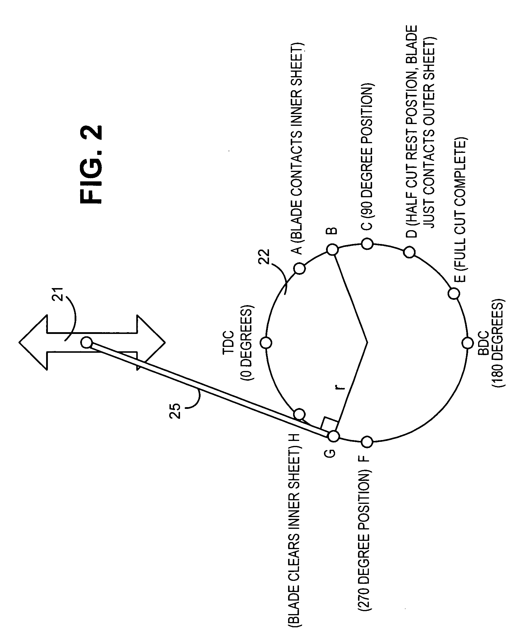
[0024]FIG. 2 is a dia...


PUM

PropertyMeasurementUnit
Angleaaaaaaaaaa
Angleaaaaaaaaaa
Angleaaaaaaaaaa

Abstract

A method for improved tuning of servo motors used to drive guillotine cutters on a high speed inserter machine. The tuning coefficient is continuously varied during the blade's cutting cycle. In a first step of the tuning process, a plurality of discrete positions in the blade cycle are selected for analysis of the optimal tuning coefficients. For these discrete positions, tuning coefficients are determined. After the tuning coefficients have been determined for the discrete locations in the blade cycle, the coefficients for the remainder of the blade cycle are determined through interpolation. In a preferred embodiment, linear interpolation is used. A digital filter then applies the measured and interpolated coefficients to the amplifier that controls the motor. In the preferred embodiment, the step of selecting the discrete positions includes selecting 90 degrees, 180 degrees, 270 degrees, and 360 degrees in a guillotine blade cycle. These four positions roughly correspond to peaks and valleys in the coefficients needed to work with the varying torques that are required over the blade cycle. By testing for the proper coefficients at those four discrete quadrant positions, the appropriate bases for linear interpolation are achieved.

Description

FIELD OF THE INVENTION[0001]The present invention relates generally to fine tuning the operation of a high speed guillotine cutter at the input portion of a high speed inserter system. In such a system, individual sheets are cut from a continuous web of printed paper for use in mass-production of mail pieces.BACKGROUND OF THE INVENTION[0002]Inserter systems, such as those applicable for use with the present invention, are typically used by organizations such as banks, insurance companies and utility companies for producing a large volume of specific mailings where the contents of each mail item are directed to a particular addressee. Also, other organizations, such as direct mailers, use inserts for producing a large volume of generic mailings where the contents of each mail item are substantially identical for each addressee. Examples of such inserter systems are the 8 series, 9 series, and APS™ inserter systems available from Pitney Bowes Inc. of Stamford, Conn.[0003]In many respe...

Claims


Application Information

Patent Timeline
IPC IPC(8): B26D1/08B26D7/26
CPCB26D1/085B26D5/14B26D5/00Y10T83/0467Y10T83/2192Y10T83/4493Y10T83/586Y10T83/0519Y10T83/0476Y10T83/04
Inventor SUSSMEIER, JOHN W.DEPOI, ARTHUR H.LEITZ, GERALD F.
Owner DMT SOLUTIONS GLOBAL CORP
Learn More