Method and system for controlling a vapor delivery system

Inactive Publication Date: 2008-06-19
TOKYO ELECTRON LTD
View PDF14 Cites 63 Cited by
  • Summary
  • Abstract
  • Description
  • Claims
  • Application Information

AI Technical Summary

Benefits of technology

[0011]According to another embodiment, a vapor delivery system configured to be coupled to a vapor deposition system and configured to introduce a film precursor vapor to a substrate within the vapor deposition system in order to form a thin film on the substrate from the film precursor vapor is described. A precursor evaporation system is configured to evaporate a film precursor to form the film precursor vapor. A carrier gas supply system is coupled to the process chamber and the precursor evaporation system, wherein the carrier gas supply system is configured to introduce a first flow of a carrier gas to the process chamber that passes through the precursor evaporation system and receives the film precursor vapor. The carrier gas supply system is configured to introduce a second flow of the carrier gas to the process chamber through a by-pass gas line that by-passes the precursor evaporation system. A carrier gas flow control system is coupled to an output of the carrier gas supply system, and is configured to control the amount of the first flow

Problems solved by technology

In addition, plasma excitation may activate film-forming chemical reac

Method used


Image

  • Method and system for controlling a vapor delivery system
  • Method and system for controlling a vapor delivery system
  • Method and system for controlling a vapor delivery system

Examples


Embodiment Construction

[0018]In the following description, in order to facilitate a thorough understanding of the invention and for purposes of explanation and not limitation, specific details are set forth, such as a particular geometry of the deposition system and descriptions of various components. However, it should be understood that the invention may be practiced in other embodiments that depart from these specific details.

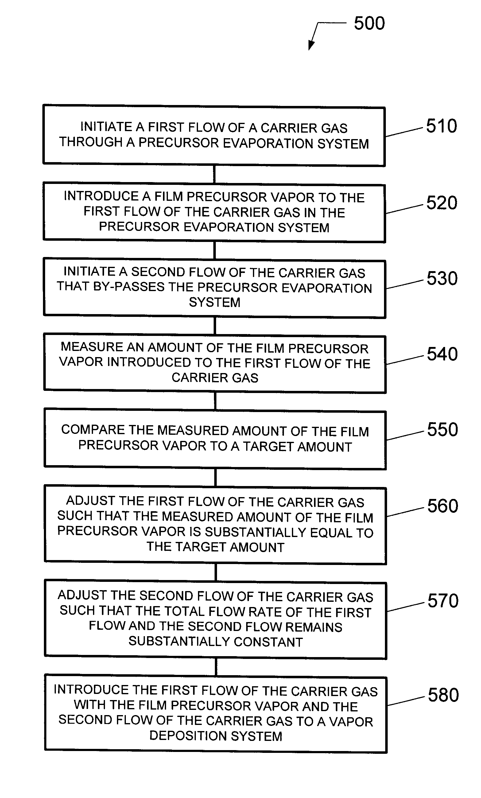
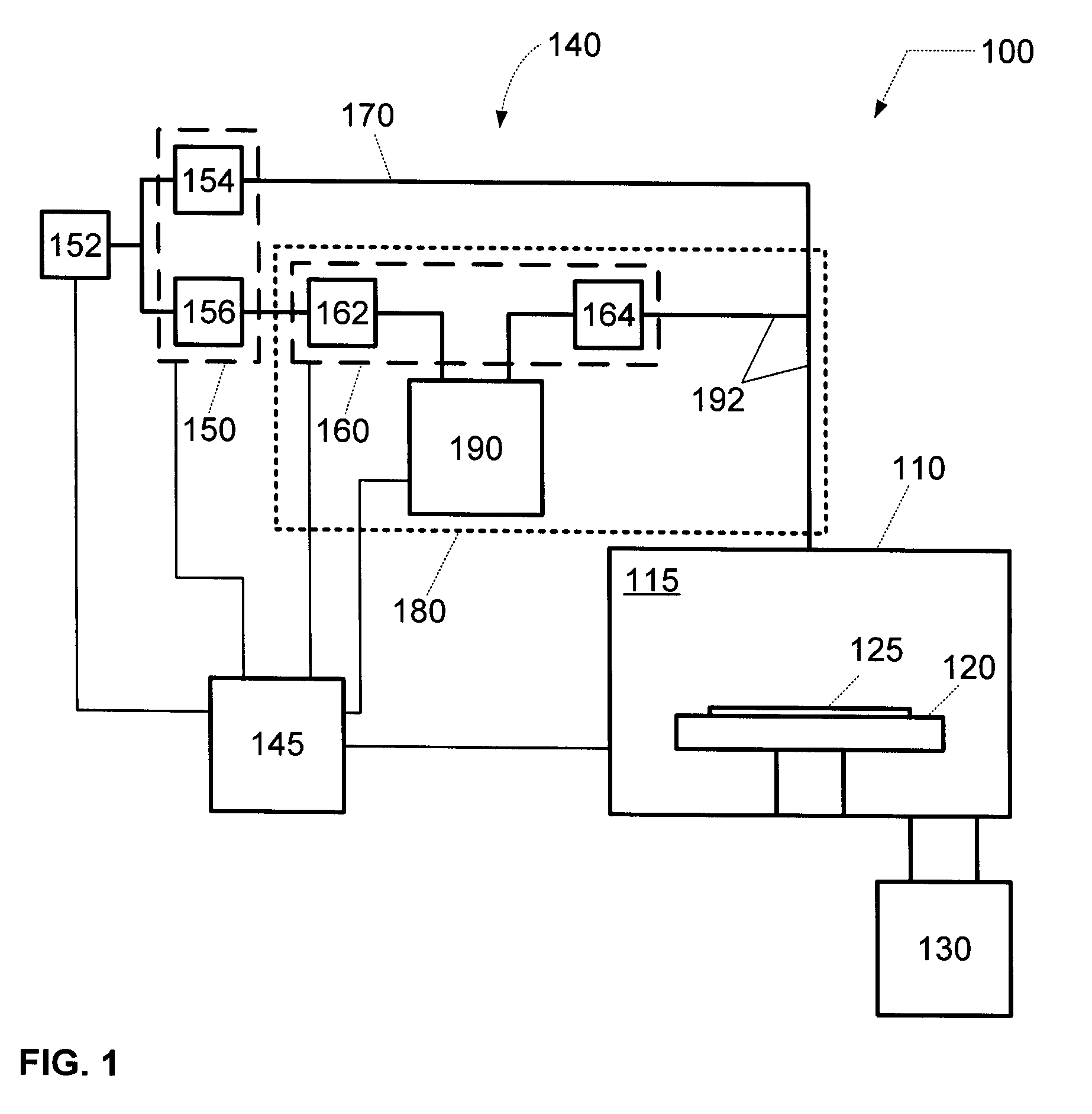
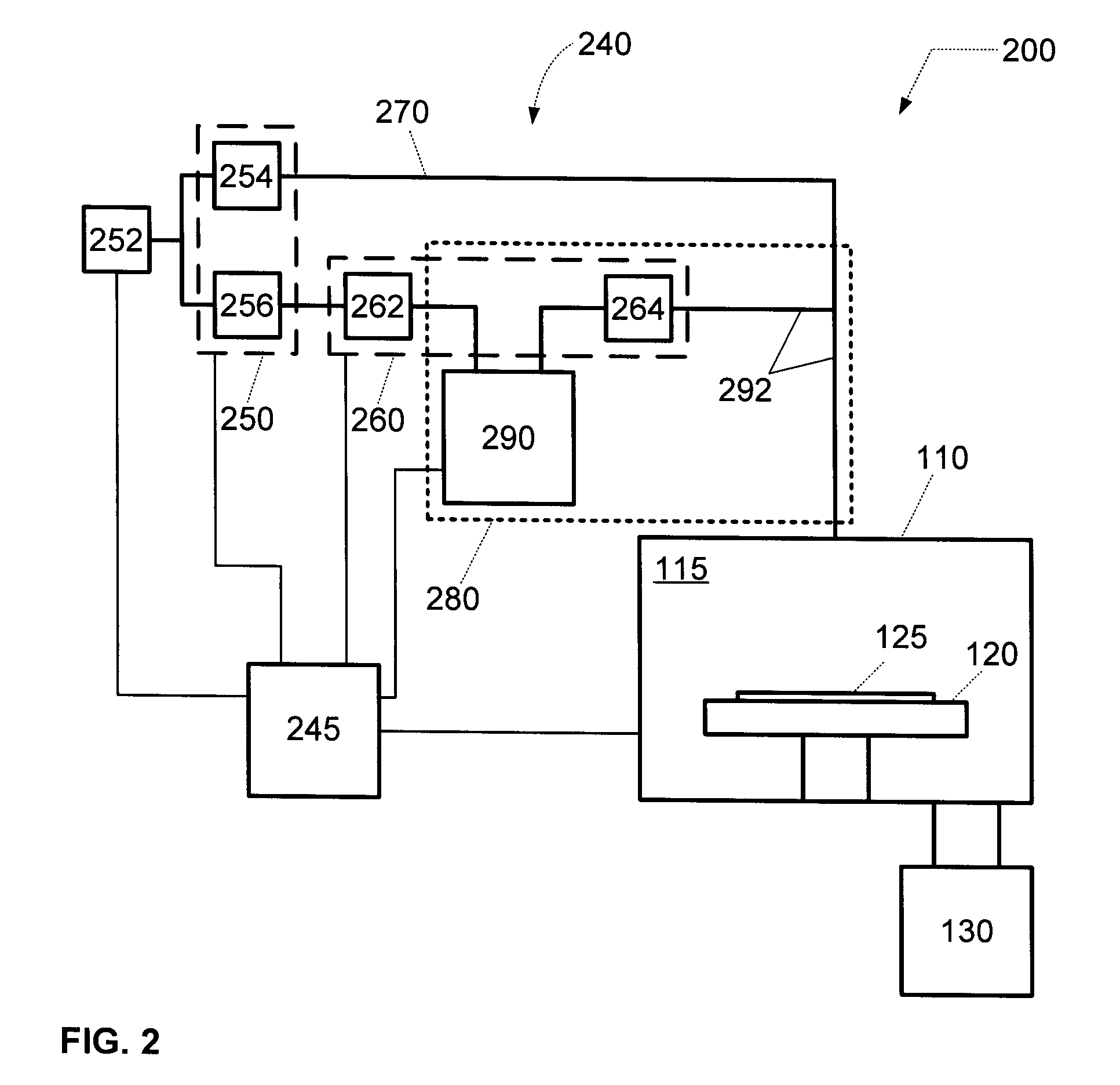
[0019]Referring now to the drawings, wherein like reference numerals designate identical or corresponding parts throughout the several views, FIG. 1 illustrates a vapor deposition system 100 for depositing a thin film, such as a metal film or a metal-containing film. The thin film may include materials suitable for use as seed layers or barrier layers in the metallization of inter- / intra-connect structures in electronic devices; materials suitable for use as gate dielectrics in electronic devices; materials suitable for use as capacitor dielectrics in DRAM devices, or the like. Fo...


PUM

PropertyMeasurementUnit
Volumetric flow rateaaaaaaaaaa
Temperatureaaaaaaaaaa
Flow rateaaaaaaaaaa

Abstract

A method and system is provided for determining and controlling the amount of film precursor vapor delivered to a substrate in a vapor deposition system, while maintaining a desired concentration of film precursor vapor within a carrier gas utilized to transport the film precursor vapor. The vapor deposition system comprises a vapor delivery system comprising a carrier gas supply system configured to supply a first flow of carrier gas that passes through a precursor evaporation system to entrain film precursor vapor and to supply a second flow of carrier gas that by-passes the precursor evaporation system. The vapor delivery system comprises a carrier gas flow control system to control the amount of the first flow of the carrier gas and control the amount of the second flow of the carrier gas. Additionally, the vapor delivery system comprises a film precursor vapor flow measurement system configured to measure an amount of the film precursor vapor introduced to the first flow of the carrier gas. Furthermore, a controller is configured to to compare the measured amount of the film precursor vapor to a target amount, to adjust the amount of the first flow of carrier gas such that the measured amount of the film precursor vapor is substantially equal to the target amount, and to adjust the amount of the second flow of the carrier gas such that the total amount of the first flow and second flow of carrier achieves a desired value.

Description

BACKGROUND OF THE INVENTION[0001]1. Field of Invention[0002]The present invention relates to a method and system for controlling a film precursor in a vapor deposition system.[0003]2. Description of Related Art[0004]During fabrication of an integrated circuit (IC), various materials are formed on and removed from the IC at various steps amongst a sequence of many steps utilized to produce the IC. For example, (dry) plasma etching is often used to remove or etch material along fine lines or within vias or contacts patterned on a substrate for production of many ICs. Alternatively, for example, vapor deposition processes are often used to form or deposit a material film along fine lines or within vias or contacts on the substrate. Such vapor deposition processes include chemical vapor deposition (CVD) and plasma enhanced chemical vapor deposition (PECVD) for gate dielectric film formation in front-end-of-line (FEOL) operations, and barrier layer and seed layer formation for metallizat...

Claims


Application Information

Patent Timeline
IPC IPC(8): B05C5/00
CPCC23C16/16C23C16/4481C23C16/36C23C16/18C23C16/52
Inventor CLARK, ROBERT D.
Owner TOKYO ELECTRON LTD
Why Eureka
Try Eureka