Solar heating system and method of forming a panel assembly therefor

a solar heating and panel technology, applied in the field of solar heating systems, can solve the problems of reducing the overall efficiency of the system employing photovoltaic cells, affecting the aesthetics of the roof-mounted components, and the relatively high cost of cells, so as to achieve the effect of convenient and quick adaptation, quick and easy installation, inspection and replacement, and convenient and fast installation and maintenan

Inactive Publication Date: 2008-06-19
SOLENERGY
View PDF47 Cites 18 Cited by
  • Summary
  • Abstract
  • Description
  • Claims
  • Application Information

AI Technical Summary

Benefits of technology

[0009]In view of the foregoing, an object of the present invention is to provide a solar heating system, and method of forming a panel assembly therefor, that allow both manufacturing and mounting of system components under a roof, either new or existing, to be accomplished more easily and quickly. Further objects of the present invention include providing a panel assembly, and associated method of forming, that do not require mounting directly to the roof, readily adapt to irregularities in actual mounting locations, allow quick and easy installation, inspection, and replacement of tubing, and do not interfere with installation or reinstallation of roofing materials.
[0012]According to another embodiment of the present invention, a method for forming an under-roof panel assembly includes forming a plurality of fasteners in a sheet material having substantially opposed first and second surfaces by partially cutting out and folding portions of the sheet material to extend from the second surface thereof. At least two sidewalls are formed by folding edge portions of the sheet material toward the second surface. A plurality of standoff tabs can also be formed by partially cutting out and folding additional portions of the sheet material to extend from the first surface thereof, the plurality of standoff tabs being dimensioned to prevent interference between the solar heating panel assembly and roofing attachment means, such as nails, screws or the like.

Problems solved by technology

While photovoltaic cells can convert solar energy directly into electricity for virtually any use, such cells remain relatively expensive.
Also, energy losses during the conversion and subsequent use of the electricity reduce the overall efficiency of systems employing photovoltaic cells.
There are several disadvantages to such systems.
For instance, building owners may find the roof-mounted components aesthetically unappealing, and may be limited to roofing types that provide a suitable mounting surface for the roof-mounted components.
Also, periodic re-roofing generally requires complete removal of the roof-mounted components, thus increasing costs.
Secure mounting usually requires penetration of the roof, increasing the risks of a leaky roof during adverse weather conditions.
Existing systems of this type largely solve the problem of aesthetics, but Applicant has found such systems to present other problems that increase the time and cost required to install and maintain such systems, as well as costs associated with roof repair and replacement in the vicinity of such systems.
Likewise, installation requires the time consuming attachment of each support member and replacement of the tubing requires each support member to be removed.
Additionally, attachment of the support members risks completely penetrating the roof, resulting in damage to roofing materials and leaks.
Moreover, installation or replacement of the roofing materials over the system, such as replacement of shingles, would likely result in damage to the support members or tubing, for instance by roofing nails dislodging support members or penetrating tubing.
While such an arrangement avoids the need to attach the legs directly to the roof, the fastening legs still abut the roof resulting in likely interference with roofing installation or replacement.

Method used


Image

  • Solar heating system and method of forming a panel assembly therefor
  • Solar heating system and method of forming a panel assembly therefor
  • Solar heating system and method of forming a panel assembly therefor

Examples


Embodiment Construction

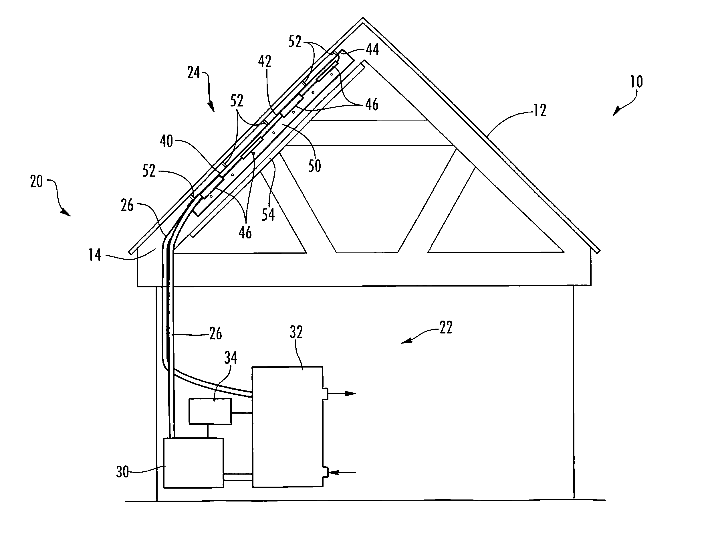
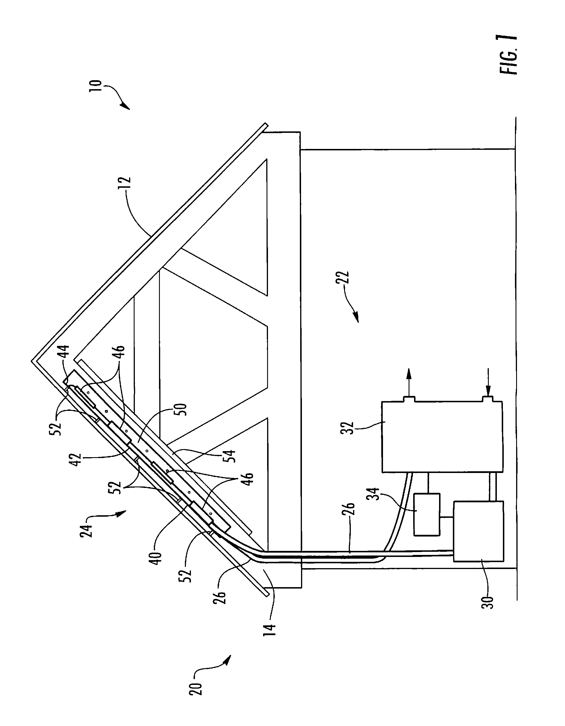
[0018]Referring to FIG. 1, building 10 includes a roof 12 supported by a plurality of trusses 14 (only one shown in FIG. 1). A solar heating system 20 includes support equipment 22, an under-roof panel assembly 24 and tubing 26 extending between the support equipment 22 and the panel assembly 24. The support equipment 22 includes a circulating pump 30, a holding tank 32 and an electronic control unit 34.

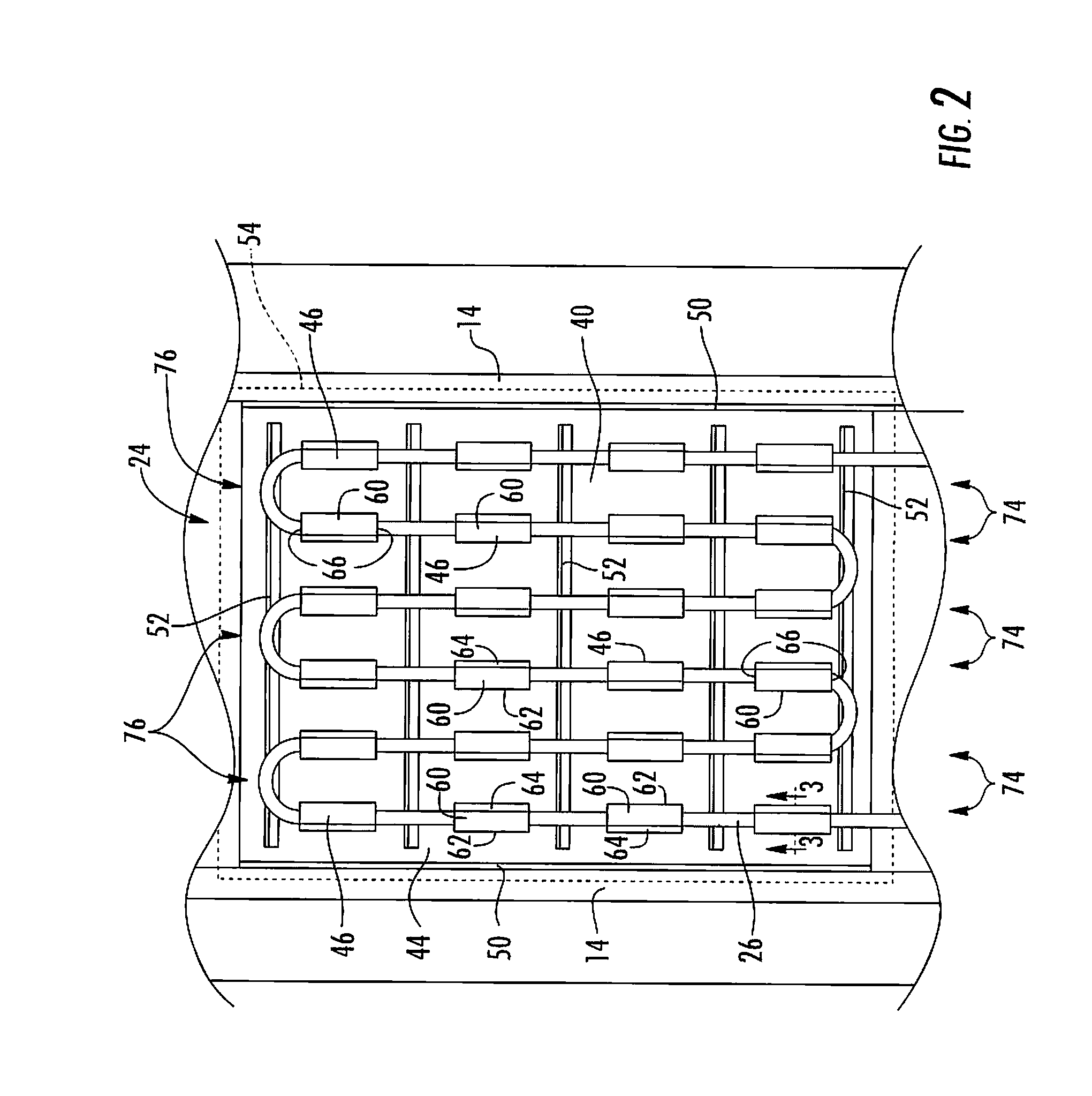
[0019]Referring to FIGS. 1 and 2, the panel assembly 24 includes a panel 40 formed of a sheet material having substantially opposed first and second surfaces 42, 44 with the first surface 42 facing toward the roof. A plurality of tubing fasteners 46 extend from, and holding a run of the tubing 26 against, the second surface 44 of the panel 40. Sidewalls 50 extend from the panel 40 and are secured to adjacent trusses 14. A plurality of standoff tabs 52 maintains a predetermined spacing between the panel 40 and the roof 12. An insulating member 54 (the insulating member 54 is removed i...


PUM

PropertyMeasurementUnit
widthaaaaaaaaaa
widthaaaaaaaaaa
lengthaaaaaaaaaa

Abstract

A solar heating system for mounting under a roof includes a panel formed of a sheet material, the panel having substantially opposed first and second surfaces and adapted for attachment under the roof with the first surface substantially facing the roof. A plurality of tubing fasteners extend outward from the second surface of the panel, and at least one run of tubing is held against the second surface of the panel by the plurality of tubing fasteners. The plurality of tubing fasteners can be partially cut-out and bent portions of the sheet material. The system can also include a sidewall formed by folding a portion of the sheet material toward the second surface along a line of weakness and standoff tabs extending from the first surface formed as partially cut-out and bent portions of the sheet material.

Description

CROSS-REFERENCE TO RELATED APPLICATIONS[0001]This application claims the benefit of U.S. Provisional Application No. 60 / 870,863, filed on Dec. 20, 2006, and U.S. Provisional Application No. 60 / 869,827, filed on Dec. 13, 2006, the contents of which applications are hereby incorporated by reference in their entirety.FIELD OF THE INVENTION[0002]The present invention relates to solar heating systems, and particularly to panel assemblies for under-roof solar heating systems and related methods of forming.BACKGROUND OF THE INVENTION[0003]As the price for fossil fuels steadily increases and the awareness of the potentially adverse environmental impact of burning fossil fuels grows, solar power is more often looked to as an alternative source of cheap, clean energy. While photovoltaic cells can convert solar energy directly into electricity for virtually any use, such cells remain relatively expensive. Also, energy losses during the conversion and subsequent use of the electricity reduce th...

Claims


Application Information

Patent Timeline
Patent Type & Authority Applications(United States)
IPC IPC(8): E04D13/18F24J2/24B21D53/04F24S10/70F24S10/75
CPCF24J2/045F24J2/268Y10T29/49355Y02E10/44Y02B10/20F24S10/755F24S20/67Y02A30/60
Inventor HANKEN, MICHAEL J.
Owner SOLENERGY
Why Eureka
Try Eureka