Crimper for binding coil

a crimping coil and crimping technology, which is applied in the field of crimping devices, can solve the problems of undesirable crimping coil ends, aesthetically unpleasant or otherwise faulty coil ends, and achieve the effect of convenient and manual configuration and convenient interchang

Inactive Publication Date: 2008-06-19
PERFORMANCE DESIGN
View PDF5 Cites 6 Cited by
  • Summary
  • Abstract
  • Description
  • Claims
  • Application Information

AI Technical Summary

Benefits of technology

[0007]In preferred embodiments, multiple crimping elements are provided that are adapted for different spiral coil diameters, wherein the elements cooperate with a brace member that is adjustable for different coil filament diameters. Thus, the preferred device may be easily and manually configured, without tools, for coils of different diameters made of filament with dif

Problems solved by technology

Prior art crimping apparatus tends to smash, smear, or otherwise deform the coil ends in a manner that is inconsistent or inaccurate and/or that results in coil e

Method used


Image

  • Crimper for binding coil
  • Crimper for binding coil
  • Crimper for binding coil

Examples


Embodiment Construction

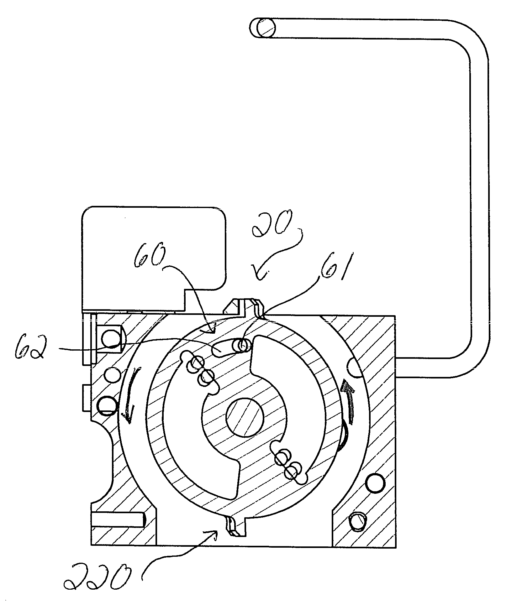
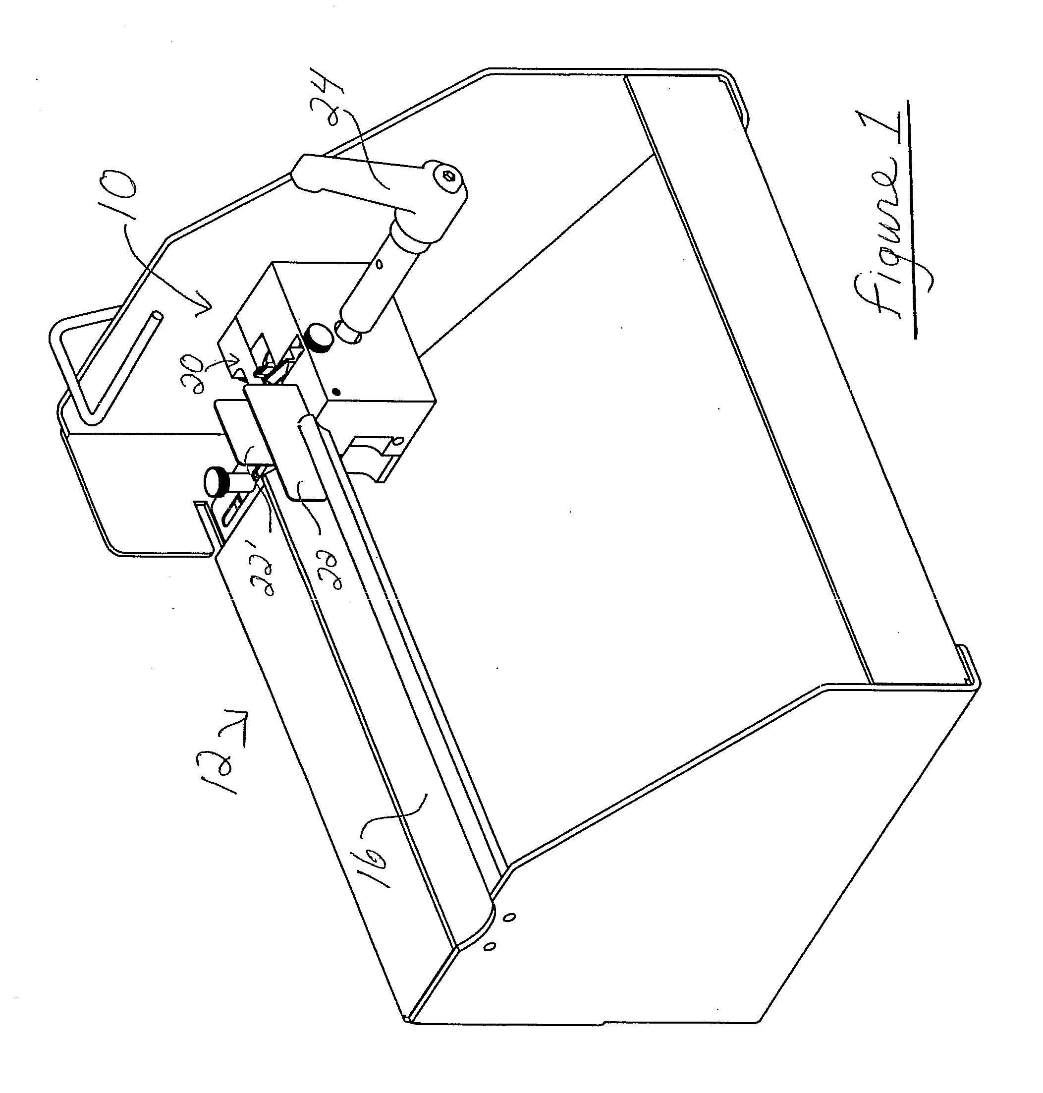
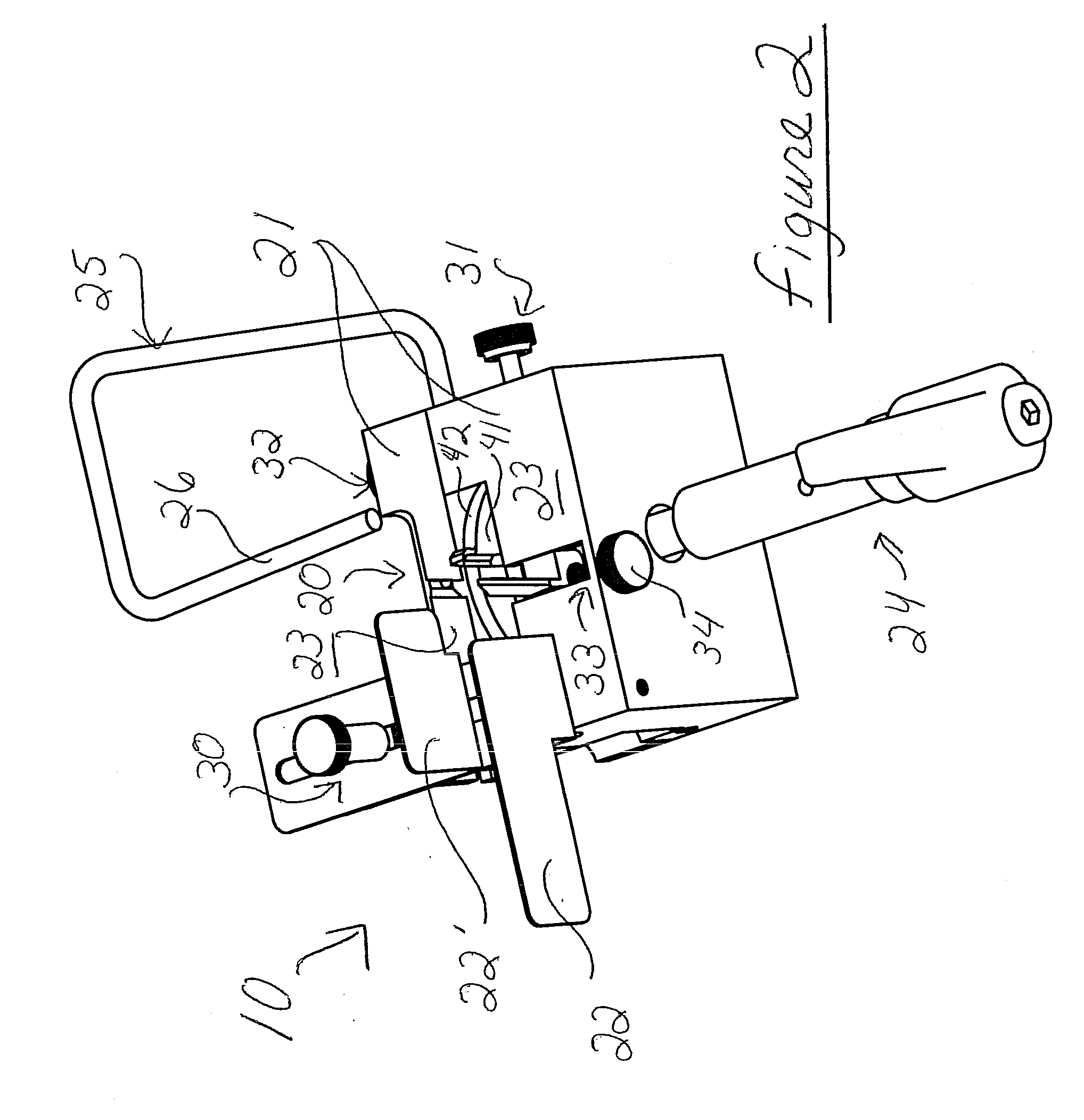
[0029]Referring to the Figures, there is shown one, but not the only, embodiments of the invented crimping device for spiral book- or pamphlet-binding coil. In most of the figures, neither the book or pamphlet, nor the coil being cut and crimped, is shown, for simplicity and to reveal the parts of the crimping set. However, it may understood, for example by viewing the embodiment of FIG. 1, that the book or pamphlet may be placed generally vertically, with the coil already inserted into the holes in the book / pamphlet sheets and received in a coil-receiving trough. This way, an end of the coil may be placed in the crimping system at one end of the trough. The book coil may be crimped on one end, and then the book and coil may be lifted up and flipped end to end to and replaced in the coil-receiving trough and crimping system for crimping of the opposite end of the coil. Alternatively, a machine may be provided with two of the invented crimpers, one for each end of the book. The prefe...


PUM

PropertyMeasurementUnit
Angleaaaaaaaaaa
Angleaaaaaaaaaa
Angleaaaaaaaaaa

Abstract

A crimper for spiral-binding coil comprises at least one, and preferably multiple, crimping assemblies including crimping elements that move generally parallel to each other to preferably cut, bend and/or reform an end of the coil for retaining the coil in the book or pamphlet. The movement of the crimping elements may be rotational in parallel planes, or translational in parallel lines. Preferably, multiple sets of crimping elements may be interchanged easily and without tools, for example, by being located on rotating members and are circumferentially spaced apart so that one set is used at a time. For each diameter of coil filament within the range of coil diameters for which a particular crimping set is designed, a member of the crimping assembly is adjusted to change the size/dimension(s) of the space into which the newly-cut end of the coil is forced, preferably adjusting that space to be slightly smaller than the diameter of the coil filament. This way, a bending member forces the newly-cut coil end against a bracing member and into the smaller space, and, in doing so, preferably heats, stretches, and generally reforms the end into a new crimped end that stays in that position over the use of the book.

Description

[0001]This application claims priority of Provisional Application Ser. No. 60 / 851,627, filed on Oct. 14, 2006, the entire disclosure of which is hereby incorporated herein by this reference.BACKGROUND OF THE INVENTION[0002]1. Field of the Invention[0003]This invention relates to a crimping device for finishing the ends of a spiral binding element or “coil.” After binding a notebook, pamphlet, or other book using a spiral binding coil, both ends of the element are conventionally bent at an angle to the axis of the coil, so that the bent ends will prevent the coil from rotating out of the book. This step in the binding process is traditionally called “crimping,” and the present invention provides an improved method and apparatus for crimping the coil ends. The present invention provides a more accurate, aesthetically-pleasing, reliable, and / or consistent crimp in the coil ends, with apparatus and methods adaptable for multiple sizes / diameters of coil and multiple diameters of filament...

Claims


Application Information

Patent Timeline
IPC IPC(8): B21F1/00
CPCB21F1/00B42B5/123B21F45/16
Inventor HOLDER, THOMAS E.
Owner PERFORMANCE DESIGN
Why Eureka
Try Eureka