Pneumatic Tire

a technology of pneumatic tires and treads, applied in the field of pneumatic tires, can solve the problems that the asymmetric tread pattern cannot go as far as to effectively improve handling stability or wear resistance, and achieve the effects of improving grip during cornering, and reducing the risk of falling o

Inactive Publication Date: 2008-06-19
BRIDGESTONE CORP
View PDF4 Cites 20 Cited by
  • Summary
  • Abstract
  • Description
  • Claims
  • Application Information

AI Technical Summary

Benefits of technology

[0071]In the pneumatic tire according to this embodiment, the number of inner-side circumferential grooves 11, 12, and 13 formed in the tread surface 1 is two or more than the number of outer-side circumferential grooves 10. Accordingly, functions of the tread surface 1 are effectively divided between the outer-side region 3 and the inner-side region 2
[0072]More specifically, in the outer-side region 3 of the tread surface 1, at least one outer-side circumferential groove 10 is formed. Accordingly, minimal drainage performance is ensured while the uneven wear of the outer-side shoulder land portion 6 is reduced, and lateral block rigidity in the inner-side region 2 is ensured to improve grip during cornering, whereby the handling stability of the pneumatic tire can be improved. On the other hand, in the inner-side region 2 of the tread surface 1, circumferential grooves of which number is two or more larger than that of the outer-side region 3 are formed. Accordingly, favorable drainage performance can be obtained, and the hydroplaning resistance of the pneumatic tire can be improved.
[0073]In addition, the plurality of lug grooves 20 formed in the inner-side shoulder land portion 4 are open to the tread edge TE1 of the inner-side shoulder land portion 4 to contribute to ensuring drainage performance. Further, since the plurality of lug grooves 20 are not open to the in

Problems solved by technology

Although the asymmetric tread pattern disclosed in Patent Document 1 can favorably improve drainage performance on a wet road surface, the asymmetric tread

Method used


Image

  • Pneumatic Tire
  • Pneumatic Tire
  • Pneumatic Tire

Examples


examples

[0093]Hereinafter, examples of tires according to the present invention will be described in detail. In order to confirm effects of the present invention, two types of tires of examples to which the present invention is applied and one type of tire of a conventional example were manufactured, and evaluation tests were carried out. It should be noted that pneumatic tires according to the present invention are not limited to ones described in the following examples, and that the present invention can be carried out by making an appropriate modification without changing the spirit of the present invention.

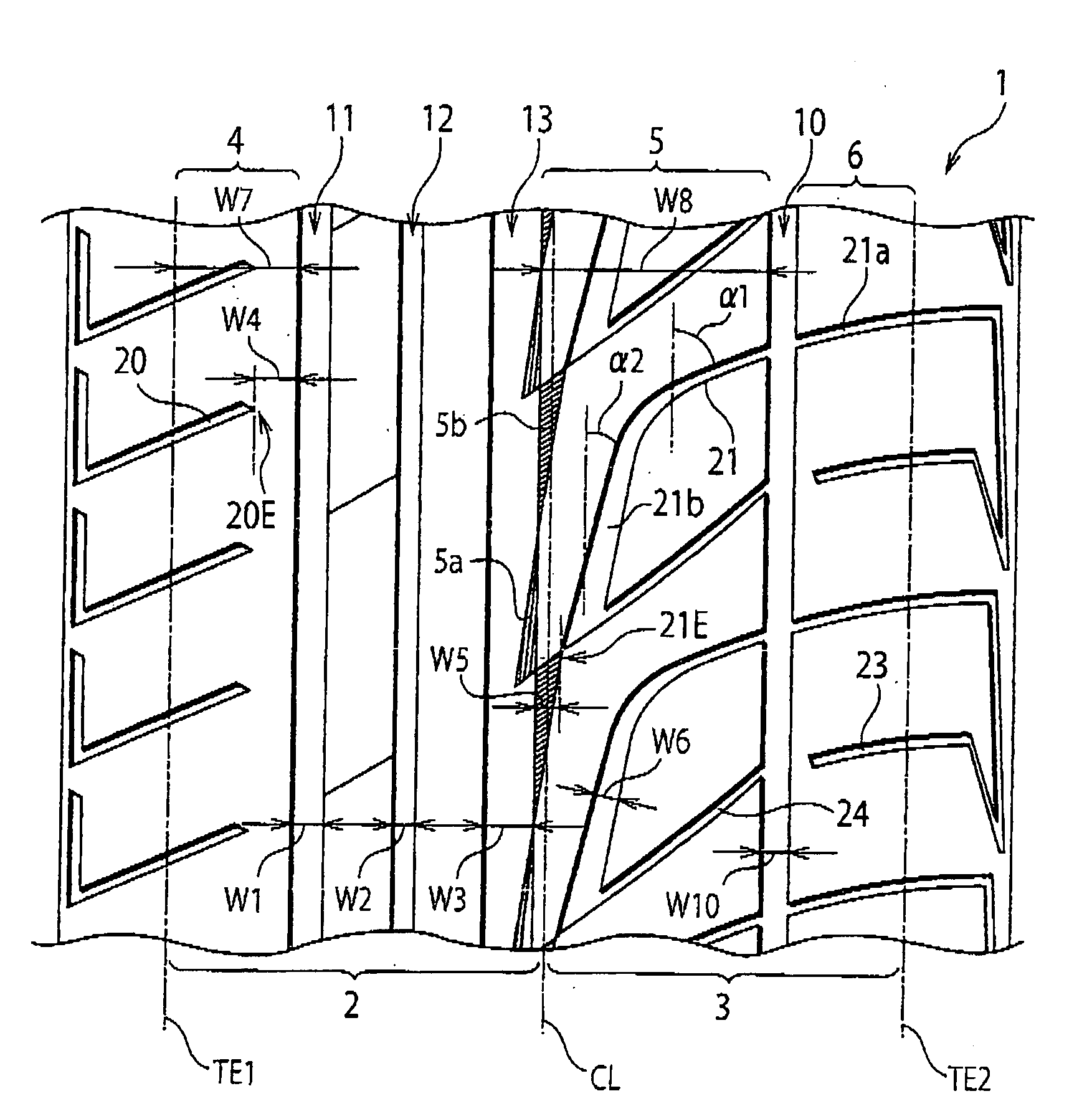
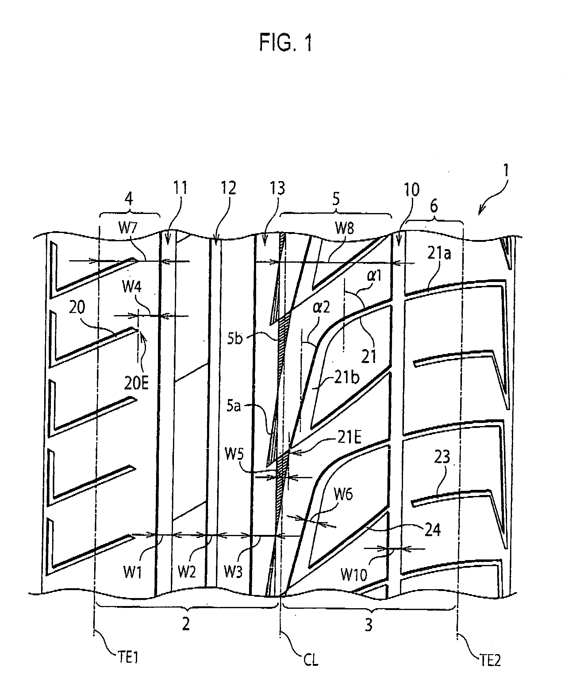
[0094]The pneumatic tire of Example 1 has a configuration equivalent to that of the tread surface 1 of the pneumatic tire of the aforementioned embodiment, as shown in FIG. 1.

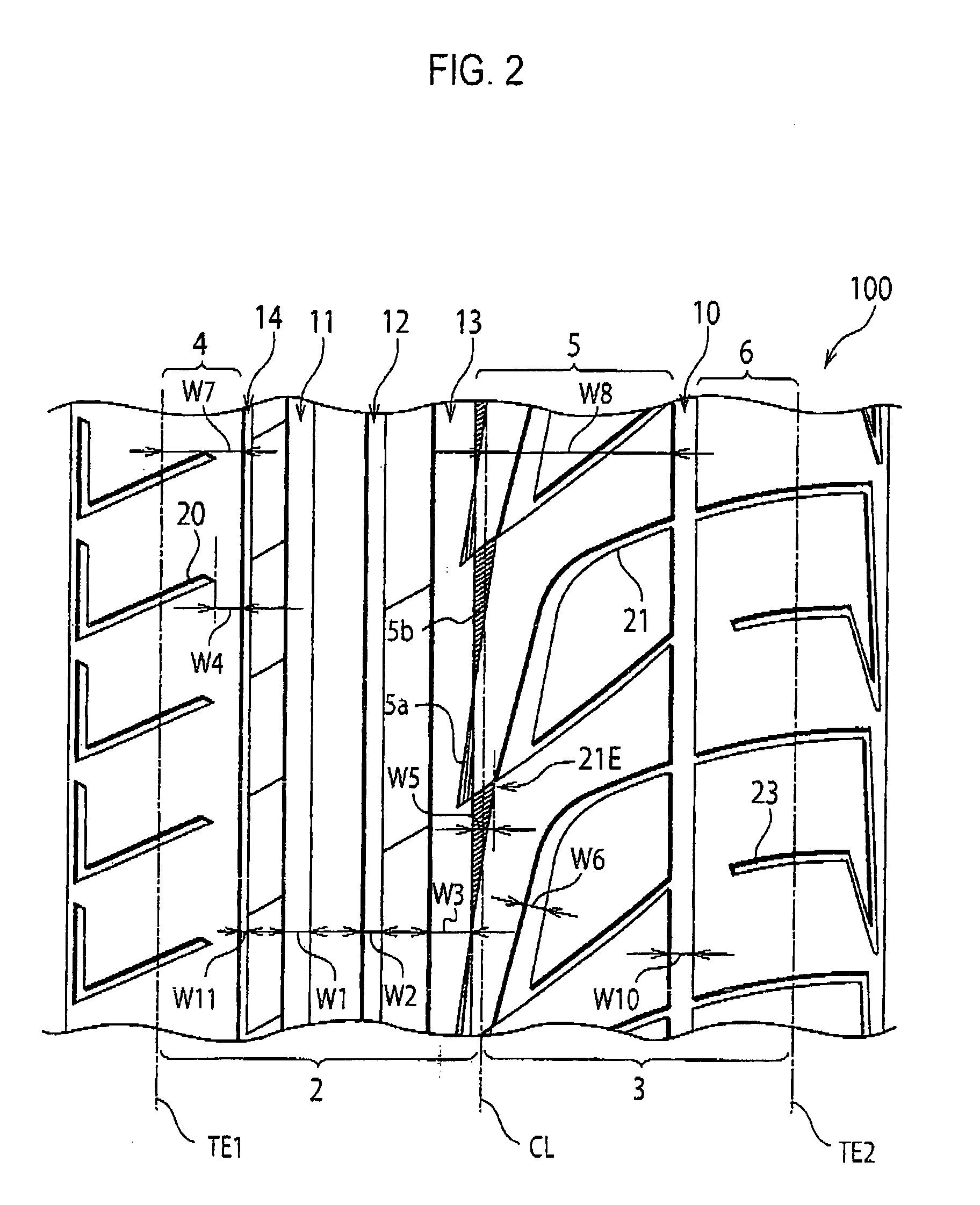
[0095]The pneumatic tire of Example 2 is a pneumatic tire having a tread surface 100 as shown in FIG. 2, and differs from the tread surface 1 shown in FIG. 1 in that another inner-side circumferential groove 14 i...

example and examples 1 and 2

Common to Conventional Example and Examples 1 and 2

[0098]Tire Size: 225 / 45R17[0099]Depth of Circumferential Groove: 8.3 mm[0100]Load: Equivalent to Actual Vehicle with Two Occupants[0101]Internal Pressure of Tire: 230 kpa

[0102]Next, dimensions of each portion of the tread surface 1 of the pneumatic tires of Examples 1 and 2 are shown in Tables 1 and 2.

TABLE 1Example 1Inner-SideNumber of Circumferential3RegionGroovesCircumferential Groove8.0 mm11's Width (W1)Circumferential Groove5.0 mm12's Width (W2)Circumferential Groove12.0 mm13's Width (W3)Lug Groove 20's Width3.0 mmDistance from Lug Grooves34.0%20 (W4)(Percentage of ShoulderLand Portion's Width W7)Outer-SideNumber of Circumferential1RegionGroovesCircumferential Groove7.0 mm10's Width (W10)Continuous Lug Groove3.0 mm (Shoulder Portion21's Width6)Continuous Lug Groove3.0 mm (Near Opening of21's Width (W6)Circumferential Groove10)Continuous Lug Groove7.5 mm (Near End 21E)21's Width (W6)Distance from Continuous12.5% (Percentage ofLu...


PUM


Abstract

On a tread surface 1 of a pneumatic tire, at least one circumferential groove is formed on an outer-side region 3 in a vehicle width direction, at least three circumferential, which number is two or more larger than the outer-side region 3, grooves are formed on an inner-side region 2 in the vehicle width direction. A plurality of lug grooves 20 are formed on the tread surface 1, open to a tread edge TE1 of the inner-side region 3, extend in a direction toward circumferential groove 11, and terminate without opening to circumferential groove 11. A plurality of continuous lug grooves 21 are formed on the tread surface 1, open to a tread edge TE2 of the outer-side region 3, extend in a direction toward the circumferential groove 13, continue to the central land portion 5 intersecting the circumferential groove 10, and terminate without opening to the circumferential groove 13 which borders the central land portion 5, among the three second-region circumferential grooves 11, 12, 13.

Description

TECHNICAL FIELD[0001]The present invention relates to a pneumatic tire having an asymmetric tread pattern. In particular, the present invention relates to a pneumatic tire having improved handling stability on a dry road surface and improved drainage performance on a wet road surface, and also having improved ride quality, improved low-noise performance, and improved wear resistance.BACKGROUND ART[0002]Heretofore, pneumatic tires each having a tread pattern which is asymmetric between outer and inner sides of a vehicle with respect to the vicinity of the tire equator when it is attached to a vehicle have been proposed. Generally, in a pneumatic tire having such an asymmetric tread pattern, on its tread surface, an outer side region of a vehicle, to be placed on the outer side of the vehicle, is provided with a pattern in which importance is placed on handling stability, and an inner side region of the vehicle, to be placed on the inner side of the vehicle, is provided with a pattern...

Claims


Application Information

Patent Timeline
IPC IPC(8): B60C11/03
CPCB60C11/13B60C11/1384B60C11/0304B60C19/001B60C11/1392
Inventor OCHI, NAOYA
Owner BRIDGESTONE CORP
Why Eureka
Try Eureka