Superconducting matrix fault current limiter with current-driven trigger mechanism

a superconducting matrix and trigger mechanism technology, applied in the direction of electric devices, emergency protective circuit arrangements, emergency protective arrangements for limiting excess voltage/current, etc., can solve the problems of material damage and hot spots generated, and achieve the effect of prolonging heating

Inactive Publication Date: 2005-10-25
SUPERPOWER INC
View PDF8 Cites 21 Cited by
  • Summary
  • Abstract
  • Description
  • Claims
  • Application Information

AI Technical Summary

Benefits of technology

[0004]Briefly, in accordance with one embodiment of the present invention, a superconducting matrix fault current limiter (MFCL) is provided which has a trigger matrix section connected in series with a current limiting matrix section, the trigger matrix section has at least one trigger matrix element. Multiple trigger matrix elements can be connected in parallel within a trigger matrix. Each trigger element has at least one non-inductively arranged superconducting component. The superconducting component, herein referred to as trigger superconductor, is electrically connected in series with an inductor made of electrically conductive material to form a superconducting trigger mechanism. The series inductor is physically disposed around the trigger superconductor in such a way so that the magnetic field generated by the current in the series inductor will be uniformly applied to the trigger superconductor. Under the normal operation condition, the magnetic field generated by the steady current is small enough so that it will not seriously degrade the critical current level of the trigger superconductor. Once there is a fault, the current surge will immediately generate a sufficiently large magnetic field to quench the trigger superconductor. This triggering will happen before or near the start of the quenching process therefore ensuring the...

Problems solved by technology

The non-uniformity within the superconductor could causes hot spot...

Method used


Image

  • Superconducting matrix fault current limiter with current-driven trigger mechanism
  • Superconducting matrix fault current limiter with current-driven trigger mechanism
  • Superconducting matrix fault current limiter with current-driven trigger mechanism

Examples


Embodiment Construction

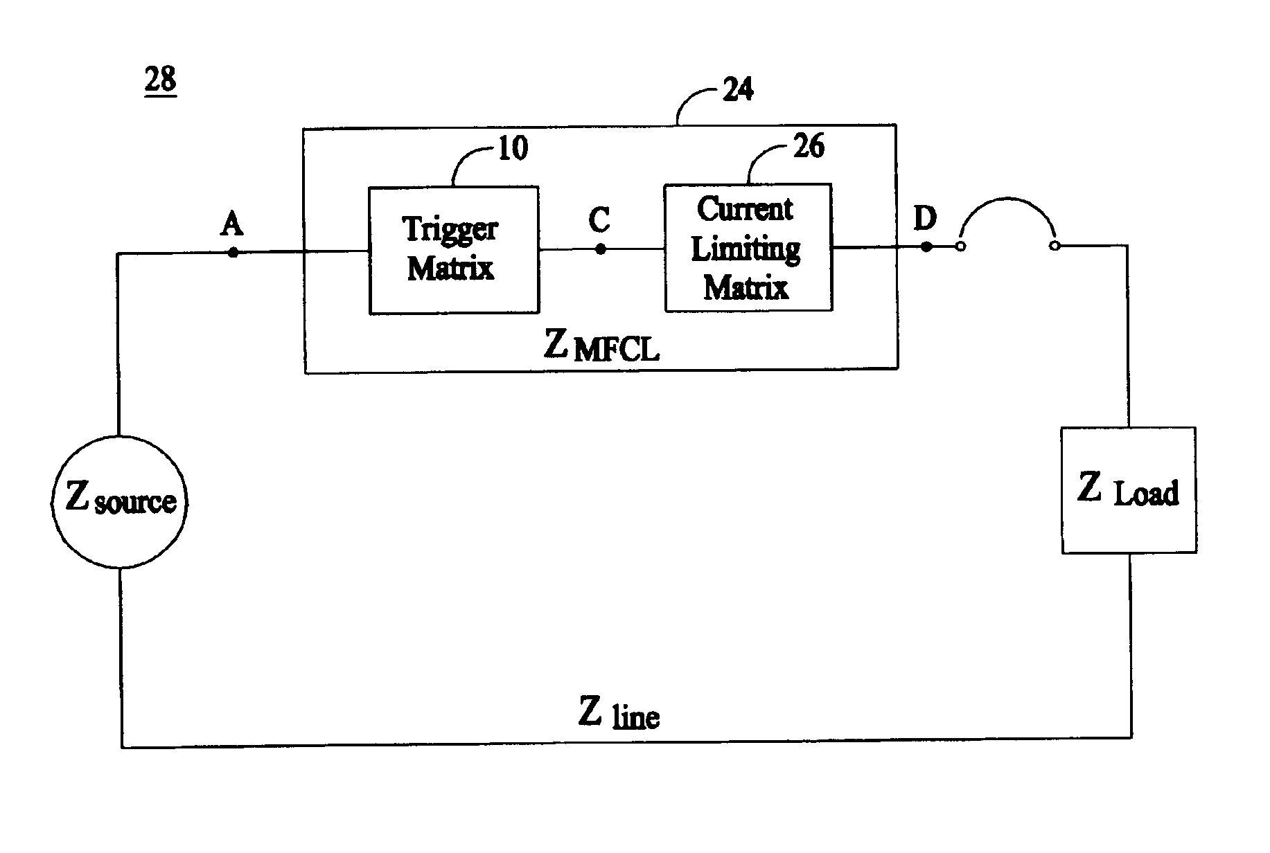
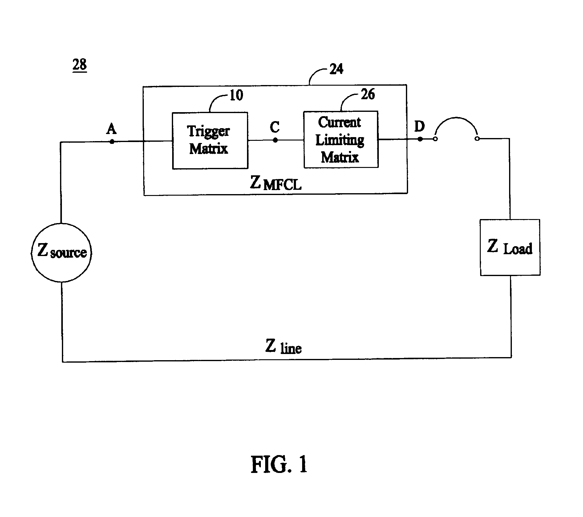
[0018]FIG. 1 shows an AC circuit 28 that is representative of a single-phase electric power system in its most general form. The AC circuit 28 includes an AC source that is a single-phase power source in a three-phased electricity transmission or distribution network with associated impedance ZSource and overall line impedance ZLine. The AC source supplies a load that has associated impedance ZLoad. Electrically connected in series between the AC source and the load is an MFCL 24 device having associated impedance ZMFCL when a fault condition occurs, and a conventional circuit breaker. Absent MFCL 24 in the AC circuit 28, the fault current level when the load is electrically shorted to ground is determined by i1=VSource / (ZSource+ZLine). However, the inclusion of MFCL 24 in the AC circuit 28 limits the fault current level to a value i2=VSource / (ZSource+ZLine+ZMFCL). As long as ZMFCL is non-zero when the fault occurs, the i2 level is lower than i1, thus achieving the fault current lim...


PUM


Abstract

A modular and scalable Matrix-type Fault Current Limiter (MFCL) that functions as a “variable impedance” device in an electric power network, using components made of superconducting and non-superconducting electrically conductive materials. An inductor is connected in series with the trigger superconductor in the trigger matrix and physically surrounds the superconductor. The current surge during a fault will generate a trigger magnetic field in the series inductor to cause fast and uniform quenching of the trigger superconductor to significantly reduce burnout risk due to superconductor material non-uniformity.

Description

BACKGROUND[0001]This invention relates generally to a current limiting device for use in electric power transmission and distribution systems and more particularly to an apparatus for triggering superconductors in a superconducting matrix fault current limiter.[0002]In an existing superconducting matrix fault current limiter (MFCL) configuration (U.S. Publication 2003 / 0021074 A1, Ser. No. 10 / 051,671, published Jan. 30, 2003, and assigned to the assignee of the present invention), a trigger matrix is connected in series with a current limiting matrix. The trigger matrix elements are used to provide necessary trigger magnetic fields to assist the transition from a superconducting state to a normal resistive state (the so-called “quenching” of a superconductor), of superconductor elements in the current limiting matrix. Using the first trigger matrix element (310-1 in the application) as an example, the magnetic fields are generated through current sharing between the superconductor tr...

Claims


Application Information

Patent Timeline
IPC IPC(8): H02H9/02
CPCH02H9/023Y02E40/69Y02E40/60
Inventor YUAN, XING
Owner SUPERPOWER INC
Why Eureka
Try Eureka