Checkpoint Efficiency Using a Confidence Indicator

a confidence indicator and checkpoint efficiency technology, applied in the field of processors, can solve the problems of reversing instruction execution, affecting the efficiency of checkpoint, and requiring subsequent instructions to be flushed,

Inactive Publication Date: 2008-06-19
ADVANCED MICRO DEVICES INC
View PDF9 Cites 10 Cited by
  • Summary
  • Abstract
  • Description
  • Claims
  • Application Information

AI Technical Summary

Problems solved by technology

Other instructions may cause exceptions (also referred to as traps or interrupts), which typically cause redirection of instruction execution to an exception handler.
Still further, speculation on some instructions may cause subsequent instructions to be flushed.
However, the speculative state may be fairly large, and thus checkpointing the state is expensive in both processor chip area (for the checkpoint storage) and in power consumption (to read and write the state).
All of these mechanisms suffer from checkpointing many instructions unnecessarily, which is an inefficient use of the checkpoint resource.

Method used


Image

  • Checkpoint Efficiency Using a Confidence Indicator
  • Checkpoint Efficiency Using a Confidence Indicator
  • Checkpoint Efficiency Using a Confidence Indicator

Examples


Embodiment Construction

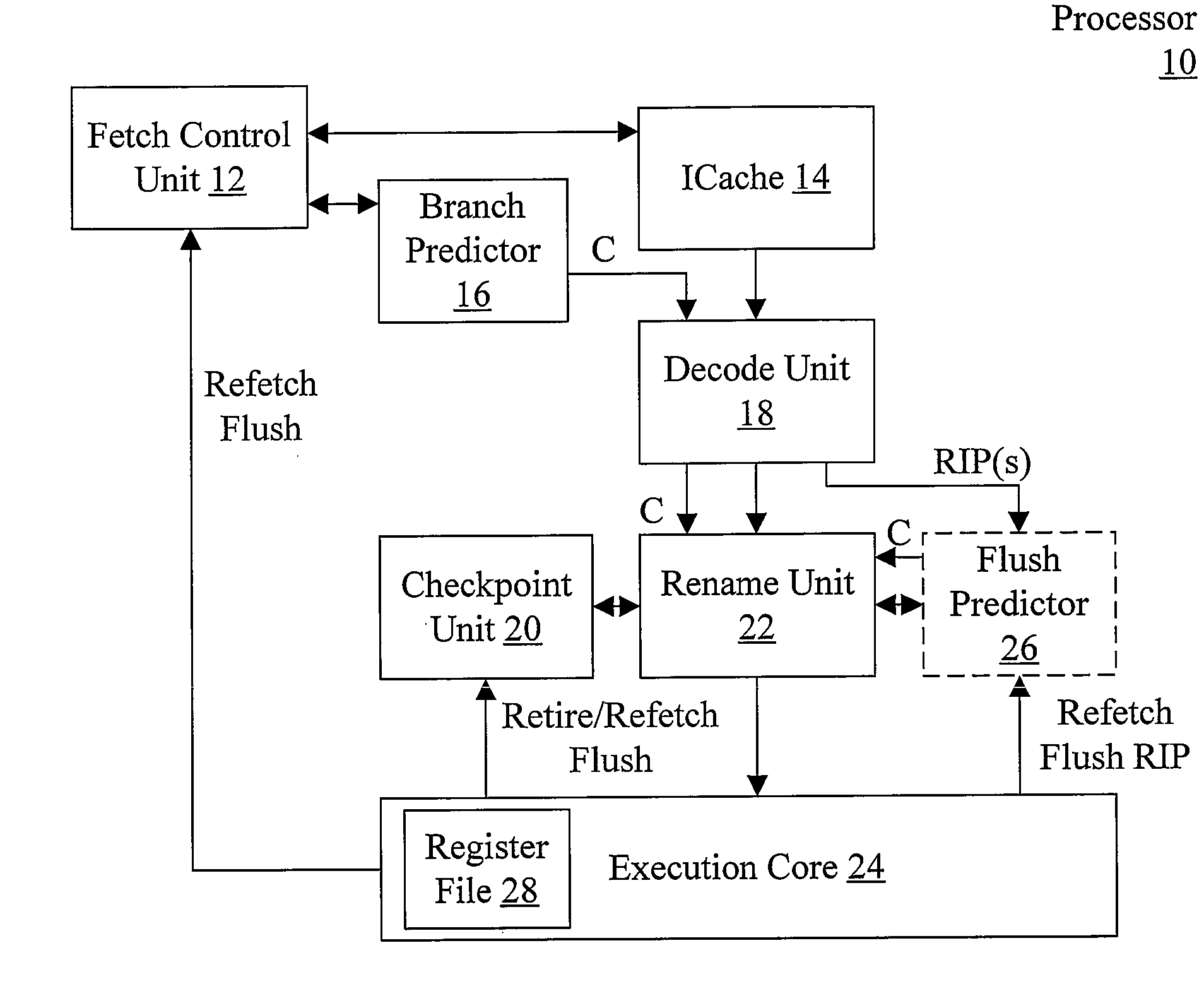
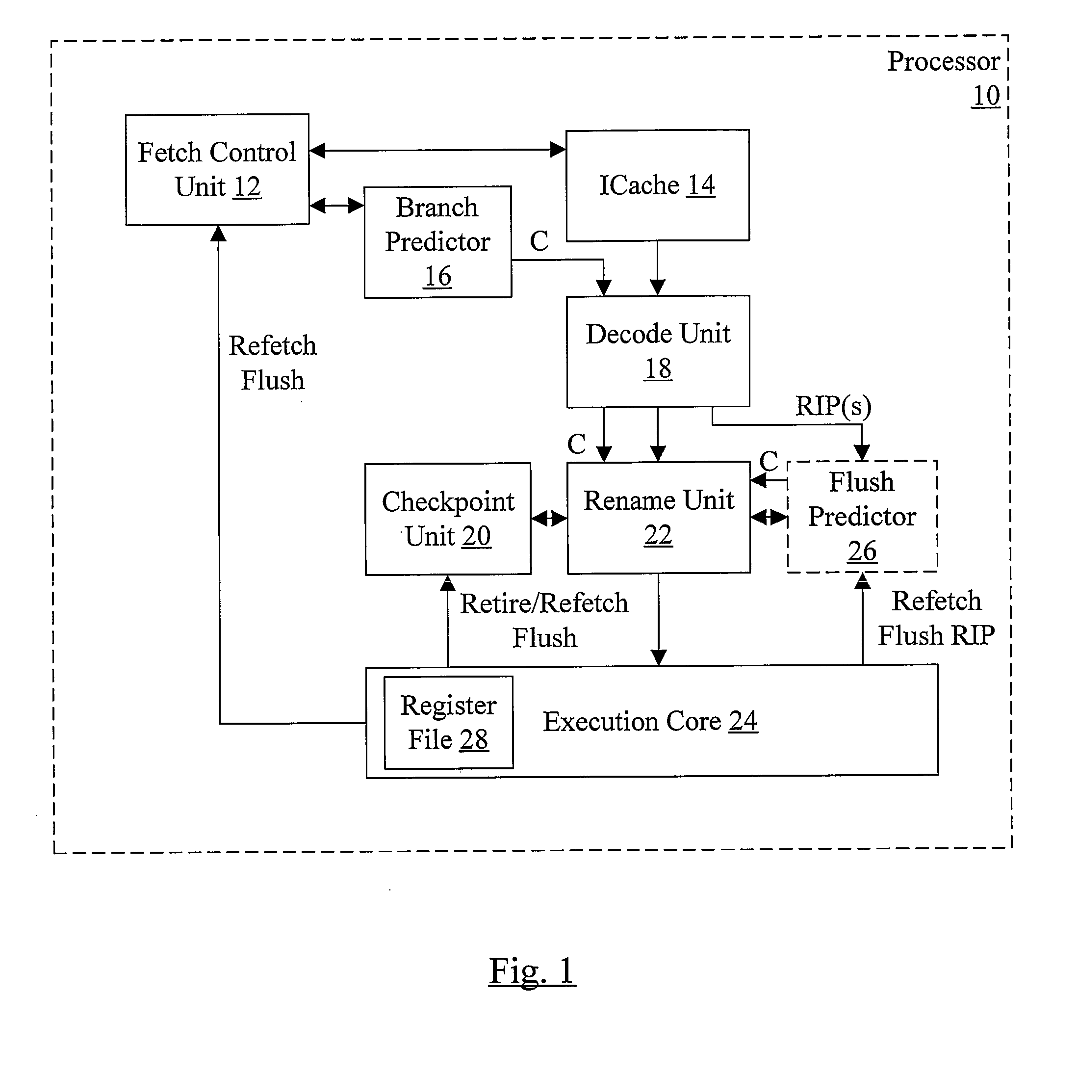
[0017]Turning now to FIG. 1, a block diagram of one embodiment of a processor 10 is shown. In the illustrated embodiment, the processor 10 comprises a fetch control unit 12, an instruction cache (ICache) 14, a branch predictor 16, a decode unit 18, a rename unit 22, an execution core 24, a checkpoint unit 20, and optionally a flush predictor 26. The fetch control unit 12 is coupled to the ICache 14, the branch predictor 16, and the execution core 24. The ICache 14 and the branch predictor 16 are further coupled to the decode unit 18, which is further coupled to the rename unit 22. The rename unit 22 is further is further coupled to the execution core 24, the checkpoint unit 20, and the flush predictor 26. The execution core 24 is further coupled to the checkpoint unit 20 an the flush predictor 26. The execution core 24 includes a register file 38.

[0018]The term operation, or instruction operation, (or more briefly “op”) will be used herein with regard to instructions executed by the...


PUM


Abstract

In one embodiment, a processor comprises a predictor, a checkpoint unit, and circuitry coupled to the checkpoint unit. The predictor is configured to predict an event that can occur during an execution of an instruction operation in the processor. Furthermore, the predictor is configured to provide a confidence indicator corresponding to the prediction. The confidence indicator indicates a relative probability of a correctness of the prediction. The checkpoint unit is configured to store checkpoints of speculative state corresponding to respective instruction operations. Coupled to receive the confidence indicator, the circuitry is configured to save a first checkpoint of speculative state corresponding to the instruction operation if the confidence indicator indicates a first level of probability of correctness. The circuitry is further configured not to save the first checkpoint if the confidence indicator indicates a second level of probability.

Description

BACKGROUND[0001]1. Field of the Invention[0002]This invention is related to the field of processors and, more specifically, to checkpointing speculative state in a processor.[0003]2. Description of the Related Art[0004]Processors often implement speculative execution as one technique to reach performance goals. Generally, speculative execution of instructions includes at least partially processing instructions, including generating speculative results, before they are known to be executed via the completion of preceding instructions in the program order. Speculative execution may include executing instructions that are subsequent to one or more predicted branch instructions (referred to as “in the shadow of” the predicted branch instructions, since a misprediction can cause the instructions in the shadow to be flushed). Instructions in the shadow of a predicted branch may also be referred to as “control speculative”, since misprediction of the branch instruction may cause the instru...

Claims


Application Information

Patent Timeline
Patent Type & Authority Applications(United States)
IPC IPC(8): G06F9/30
CPCG06F9/3806G06F9/3844G06F9/3863G06F9/3842G06F9/3834G06F9/384G06F9/3826
Inventor DHODAPKAR, ASHUTOSH S.BUTLER, MICHAEL G.
Owner ADVANCED MICRO DEVICES INC
Why Eureka
Try Eureka