Multi-basin sink

a sink and multi-basin technology, applied in water installations, household cleaners, construction, etc., can solve the problems of sinks that cannot meet their purpose, sinks are vulnerable to dent and damage, and lack of major flaws, etc., to achieve easy portability, increase the strength of sidewalls, and improve the effect of ventilation

Inactive Publication Date: 2008-06-26
LIN HSIEN YANG
View PDF8 Cites 25 Cited by
  • Summary
  • Abstract
  • Description
  • Claims
  • Application Information

AI Technical Summary

Benefits of technology

[0011]To achieve those purposes, the present invention provides a recessed accommodation space to the sink; one or a plurality of erected partitioning portion is disposed in the accommodation space to segregate it into multiple basins; one or a plurality horizontal flange protruding toward interior of the sink is disposed at a depth approximately one fourth up to three fourths below a middle section of the accommodation space at where closer to an opening of the basin to reinforce strength of sidewalls of the entire basin. Furthermore, if required, a board to place objects thereon is supported on the horizontal flange so to define a retainer in conjunction with a local inner wall of the sink for the retainer to create proper blocking function for preventing objects from being pushed to fall off.
[0012]A mobile partition is further provided to sit on the erected partitioning portion in the accommodation space and both sides of the mobile partition hold tightly against two opposite inner walls of the accommodation space for the mobile partition to provide an even higher partition in coping with use of an deeper and smaller basin.
[0013]Furthermore, one or a plurality pair of handles is disposed on one side of the board at where in relation to the horizontal flange protruding toward interior of the sink for easy portability while providing support on the horizontal flange to facilitate creating support for another height for the board.

Problems solved by technology

Accordingly, a major flaw exists since either basin serves its use only to prevent from combining both basins into a single one in coping with a larger area rinsing as may be needed.
However, it fails to satisfy its is purpose when application of a deeper and smaller basin is required.
Sinks of the prior art including those described above features the same extremely thin and fragile construction of any of those sinks at where between a highest point and a deepest point of a concave of the sink leading to that the sink is vulnerable to be dented and damaged by pressure in the course of transportation or use.

Method used


Image

  • Multi-basin sink
  • Multi-basin sink
  • Multi-basin sink

Examples


Embodiment Construction

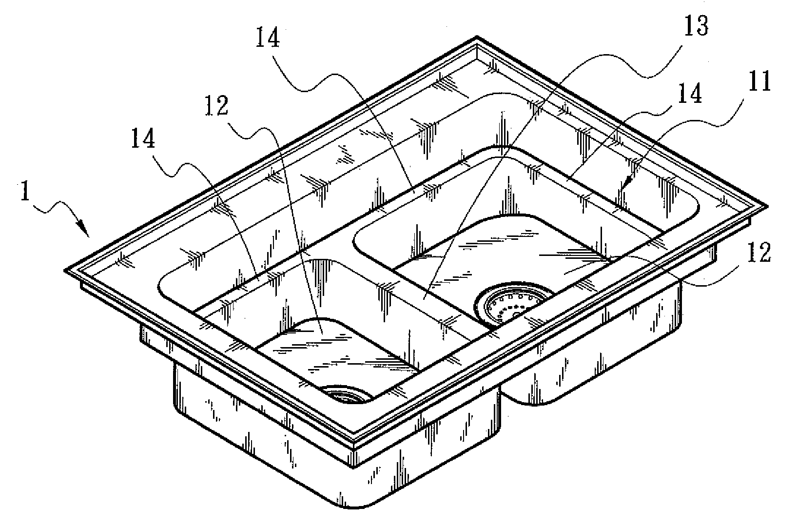
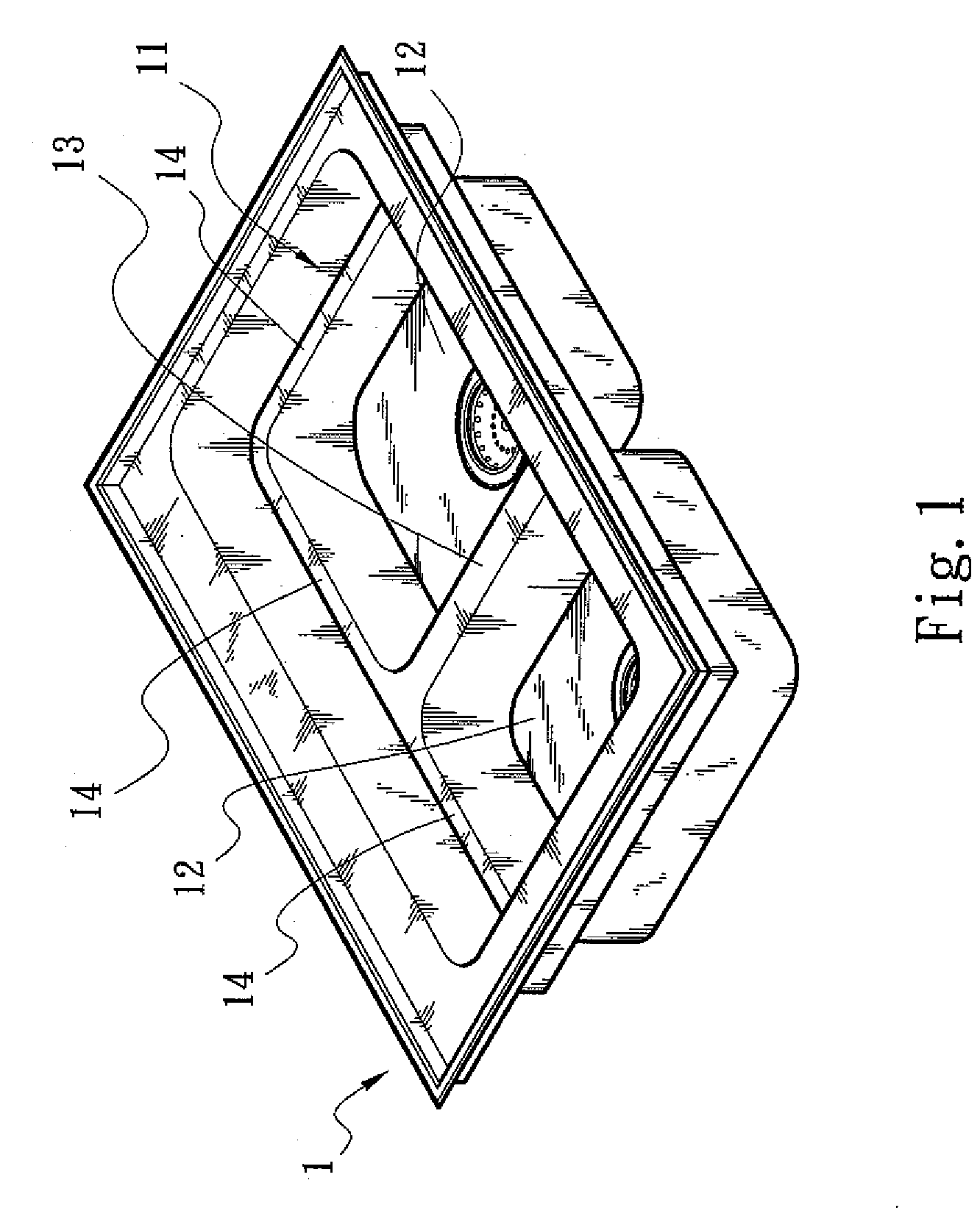
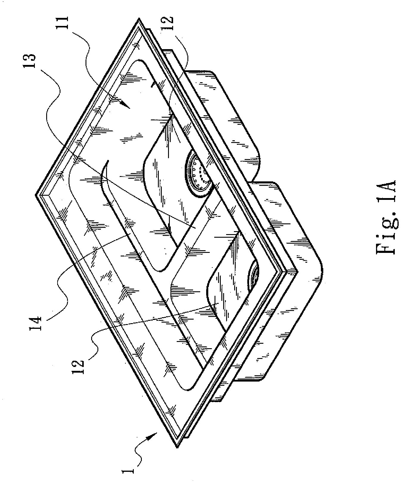
[0030]Referring to FIG. 1 showing a basic construction of the present invention, the present invention is essentially comprised of a sink 1 and an accommodation space 11 recessed from top of the sink 1; one or a plurality of partitioning portion 13 is disposed on and upwardly extending from a bottom of the accommodation space 11 in a depth approximately one fourth up to three fourths of that of the accommodation space 1 to segregate a lower half of the accommodation space 11 into multiple basins 12; one or a plurality of horizontal flange 14 protruding toward interior of the sink 1 is disposed in the accommodation space 11 at where closer to a peripheral of an opening of those basins 12; and as applicable, the horizontal flange 14 may be provided on a full peripheral as illustrated in FIG. 1 or a local part of the peripheral as illustrated in FIG. 1A.

[0031]As illustrated in FIG. 11B, a secondary horizontal flange 14A extending inwardly is disposed at where between a top edge of the ...


PUM


Abstract

A multi-basin sink includes a sink and an accommodation space recessed in the sink and segregated into multiple basins; one or a plurality of horizontal flange protruding toward interior of the accommodation space being disposed at a depth approximately one fourth up to three fourths below a middle section of the accommodation space at where closer to an opening of the basin to reinforce strength sideway of the entire sink; a board or disk laterally striding over the horizontal flange; a mobile partition being provided in and to adjust height of the partitioning portion in the sink.

Description

BACKGROUND OF THE INVENTION[0001](a) Field of the Invention[0002]The present invention is related to a multi-basin sink, and more particularly, to one that allow changed water storage area and water level.[0003](b) Description of the Prior Art[0004]Whereas more functions are demanded on a sink, kitchen sinks generally available in the market offer various constructions and functions. As disclosed in U.S. Pat. No. DES. 295065 titled“SINK”, a sink including two basins completely separated from each other permits its user to select either basin in case of small area of washing is needed for achieving a basic function of saving water consumption; a slope is disposed to one side of either or both basins to facilitate food preparation as taught in U.S. Pat. No. DES. 259439 titled “FOOD PREPARATIONSINK”; in U.S. No. Pat. DES. 324264 titled “SINK”, a graded flange is disposed to an outer peripheral over a 2-basin sink to facilitate placement of a chopping board or other objects while restri...

Claims


Application Information

Patent Timeline
Patent Type & Authority Applications(United States)
IPC IPC(8): E03C1/186A47L17/02
CPCE03C1/18A47L17/02
Inventor LIN, HSIEN-YANG
Owner LIN HSIEN YANG
Why Eureka
Try Eureka