Filter fuel assembly

a technology of fuel filter and assembly, which is applied in the direction of cartridge filter, filtration separation, and separation process, etc., can solve the problems of real problems affecting the quality of the fuel and generating contaminants, and causing damage, so as to reduce the maintenance cost of the engine system, reduce the performance of the engine, and increase the productive life of the engine and the fuel filtering line system.

Inactive Publication Date: 2008-06-26
DEL PINO SUAREZ CARLOS
View PDF39 Cites 5 Cited by
  • Summary
  • Abstract
  • Description
  • Claims
  • Application Information

AI Technical Summary

Benefits of technology

[0008]The filter assembly allows the fuel flow to pass from the tank directly to the top of the removable easy to clean filtering unit, whereby the solid and semisolid contaminants are trap on the inside area of the filter unit. After filtration, the fuel flow may be redirected to the tank if the filter is installed to clean the tank fuel or alternatively, it may be directed to the engine if the filter device has been installed between the tank and the engine fuel filtering system. When used in the tank-engine line, the herein disclosed fuel filter assembly is able to filter contaminants such as algae, fungus, microbial growth, rust and similar ones that would degrade the fuel and would also decrease the performance of the engine if left within the fuel. The said fuel filter assembly increases the productive life of the engine and the fuel filtering line system, reducing the maintenance cost of the engine system of the vehicle.

Problems solved by technology

It is well known that the presence of particulates or contaminants in stored fuel liquids such as diesel, jet fuel, kerosene, gasoline, heating oil and similar liquids represents a real problematic situation affecting negatively the quality of the fuel and the performance of engines requiring the said fuel for its intended functioning.
Many of the said contaminants are generated by the presence of water in the fuel.
These fuel contaminants may be transported together with the fuel flow to the fuel filtration conduits, engines and fuel consuming devices producing expensive damages to the said filtration lines engines and devices.
The said particulates or contaminants produce fuel degradation, clogging of filters and even they may induce the engine failure.
As possible solutions to this problem, multiple sophisticated and expensive solutions have been presented by the prior art.
However, these alternatives do not avoid the constant water condensation in the tank or fuel container and thus, the proposed alternatives cannot eliminate the constant generation of the said contaminants.

Method used


Image

  • Filter fuel assembly
  • Filter fuel assembly
  • Filter fuel assembly

Examples


Embodiment Construction

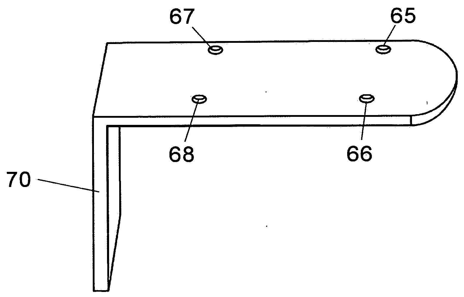
[0021]Detailed embodiments of the instant invention are disclosed herein, however it is to be understood that the disclosed embodiments are only examples and that the disclosed invention may be embodied in alternative forms and / or in other possible variations. The particular structural and functional details disclosed herein should not be interpreted as limiting, since they are presented as a basis for the claims and with the main objective of teaching those skilled in the art to make and use the instant invention. Particularly, shapes of the required units comprising the fuel filter assembly disclosed herein may be substituted by other alternative shapes without departing from the scope of the instant invention. Relative size of the fuel filter assembly and its units may vary depending of the volume of the flow requiring filtration and / or the amount of contaminants containing in the fuel. It is understood that the filter assembly may be use to separate solid material from non-fuel ...


PUM

PropertyMeasurementUnit
mesh sizeaaaaaaaaaa
mesh sizeaaaaaaaaaa
pressureaaaaaaaaaa

Abstract

The present invention describes a fuel filter assembly useful in the purification of fuels such as diesel, gasoline, jet fuel, kerosene, heating oil and similar liquids. The fuel filter assembled herein described separates solids and semisolids particulates such as algae, microbial growth, fungi and the like from fuel, providing a much cleaner fuel to secondary fuel system, engine and fuel consuming devices. The said fuel filtering assembly comprises a removable lid mounted at the top of an upright vertical housing, a non-disposable removable filter unit enclosed in the internal cavity of the said housing and a multi-purpose base comprising fuel inlet and fuel outlet as internal passages within the said base.

Description

FIELD OF THE INVENTION[0001]The present invention relates to a filter assembly and method of separation of organic and inorganic particulates from liquids. More particularly, the invention is directed to a filter assembly and methods of using the said assembly in the purification of organic liquids such as fuels from solids and semisolids particulates such as algae, fungus, microbial growth, rust and the like.BACKGROUND OF THE INVENTION[0002]It is well known that the presence of particulates or contaminants in stored fuel liquids such as diesel, jet fuel, kerosene, gasoline, heating oil and similar liquids represents a real problematic situation affecting negatively the quality of the fuel and the performance of engines requiring the said fuel for its intended functioning. Many of the said contaminants are generated by the presence of water in the fuel. Once water is condensed in the fuel container, it provides a rich environment for the bacterial, fungus, algae and other microbial ...

Claims


Application Information

Patent Timeline
Patent Type & Authority Applications(United States)
IPC IPC(8): B01D35/00
CPCB01D29/232B01D29/58
Inventor SUAREZ, CARLOS DEL PINO
Owner DEL PINO SUAREZ CARLOS
Why Eureka
Try Eureka