
Systems and methods for an exhaust gas treatment system

a technology of exhaust gas treatment and treatment system, which is applied in the direction of exhaust treatment electric control, line-transmission details, instruments, etc., can solve the problems of reducing the efficiency of the catalyst or particulate filter, the ceramic brick may crack, and the back pressure of the exhaust system may be increased, so as to reduce the efficiency of the catalyst or particulate filter, the effect of reducing the regulated emissions and increasing the back pressure of the exhaust system

Inactive Publication Date: 2013-05-16
FORD GLOBAL TECH LLC
View PDF5 Cites 11 Cited by
  • Summary
  • Abstract
  • Description
  • Claims
  • Application Information

AI Technical Summary

Benefits of technology

The patent text is about an exhaust gas treatment device used in engines to reduce regulated emissions. One issue that can occur is that the ceramic brick used in the device can crack due to various factors like debris or a degraded support system. This can lead to reduced efficiency of the device, increased back pressure in the exhaust system, and reduced engine performance, as well as increased regulated emissions. The patent aims to address this issue to improve the performance and efficiency of the exhaust gas treatment device.

Problems solved by technology

Due to various conditions, such as debris striking the catalyst or particulate filter or a degraded support system for the catalyst or particulate filter, the ceramic brick may crack.
As such, efficiency of the catalyst or particulate filter may be reduced resulting in increased back pressure in the exhaust system and reduced engine performance and / or an increase in regulated emissions.
The wire may be wrapped around the catalyst such that degradation of the catalyst, such as cracking, may result in degradation of the wire.

Method used


Image

  • Systems and methods for an exhaust gas treatment system
  • Systems and methods for an exhaust gas treatment system
  • Systems and methods for an exhaust gas treatment system

Examples


Embodiment Construction

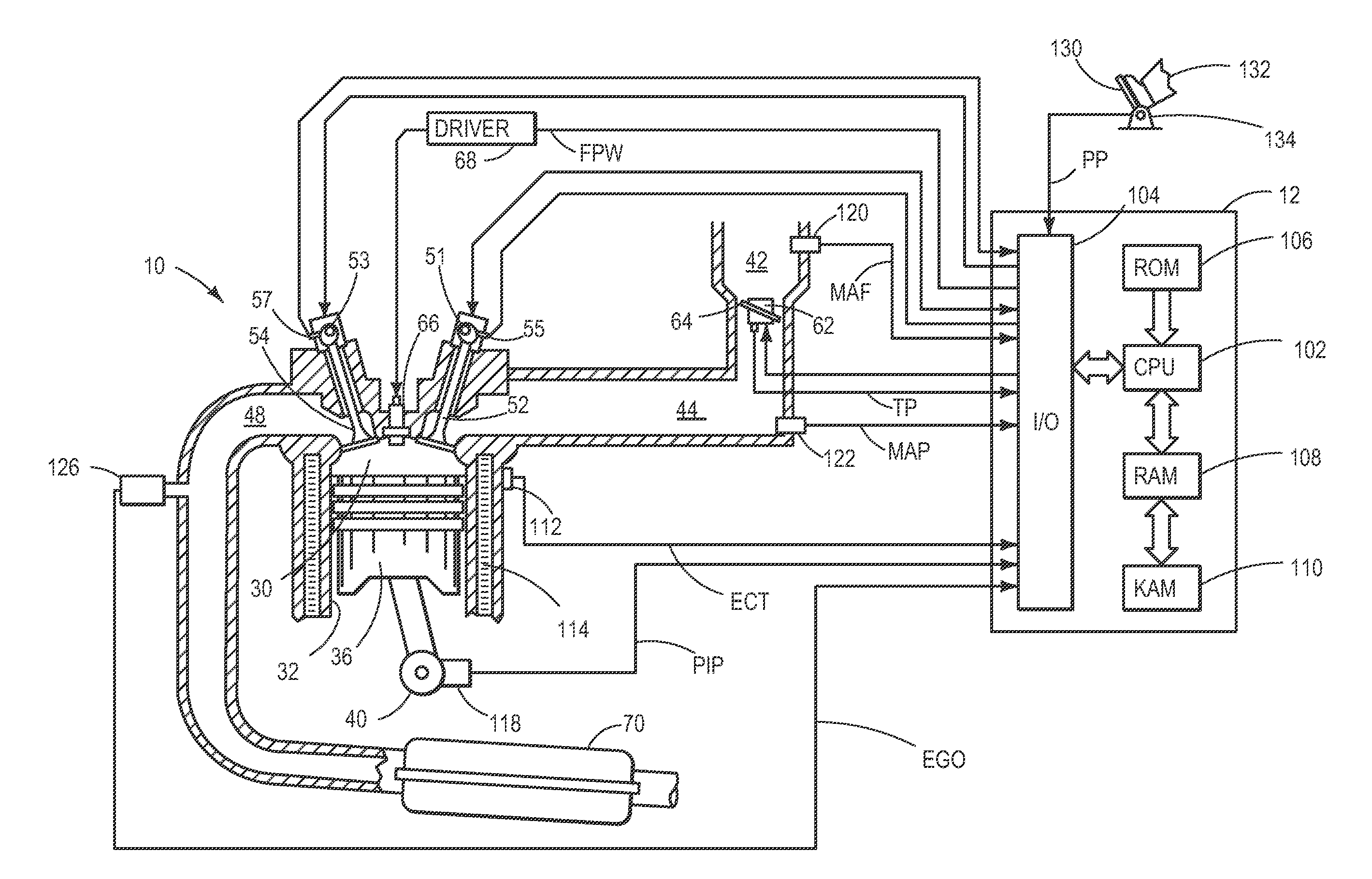
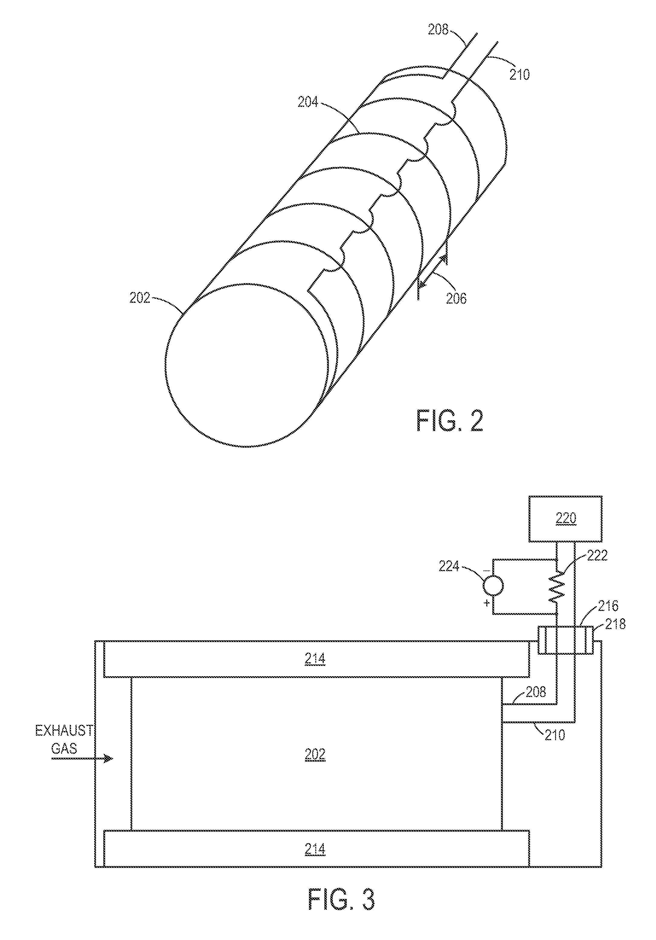
[0011]The following description relates to various embodiments of systems and methods for an exhaust system which includes an exhaust gas treatment device. In one example embodiment, a system comprises a catalyst and a wire wrapped around an exterior of the catalyst. The system further comprises a sensor configured to electrically couple ends of the wire and to monitor electrical continuity of the wire. In such a configuration, the wire is contiguous with the exterior of the catalyst such that if degradation such as cracking of the catalyst occurs, degradation of the wire may also occur. As a result, continuity of the wire may be reduced or broken and degradation of the catalyst may be indicated. In some examples, the wire may be wrapped around the exterior of the catalyst in a spiral configuration such that one wire may cover a greater surface area of the catalyst and only a single wire is needed to monitor the catalyst. Further, in some embodiments, the wire may be coupled to a re...


PUM


Abstract

Various systems and methods are provided for an exhaust gas treatment system. In one example, a system includes an exhaust gas treatment device and a wire wrapped around an exterior circumference of the exhaust gas treatment device. Continuity of the wire is monitored such that degradation of the wire due to degradation of the exhaust gas treatment device is indicated.

Description

TECHNICAL FIELD[0001]The present application relates to methods and systems for diagnosing degradation of a component of an exhaust gas treatment system coupled to an internal combustion engine.BACKGROUND AND SUMMARY[0002]An exhaust gas treatment device may be included in an exhaust system of an engine in order to reduce regulated emissions. In one example, the exhaust gas treatment device may include a catalyst or particulate filter which is formed of a ceramic brick. Due to various conditions, such as debris striking the catalyst or particulate filter or a degraded support system for the catalyst or particulate filter, the ceramic brick may crack. As such, efficiency of the catalyst or particulate filter may be reduced resulting in increased back pressure in the exhaust system and reduced engine performance and / or an increase in regulated emissions.[0003]The inventors herein have recognized the above issue and have devised an approach to at least partially address it. Thus, in one...

Claims


Application Information

Patent Timeline
Patent Type & Authority Applications(United States)
IPC IPC(8): F01N3/18G01R31/02F01N9/00
CPCF01N3/2026F01N2410/06F01N11/00Y02T10/26F01N2560/02Y02T10/12
Inventor SLOSS, JEFFREY DAVID
Owner FORD GLOBAL TECH LLC
Learn More