Methods and system for operating an exhaust valve of an internal combustion engine

a technology of internal combustion engine and exhaust valve, which is applied in the direction of valve arrangement, machine/engine, output power, etc., can solve the problems of reducing the possibility of untimely exhaust valve opening, reducing engine efficiency, and reducing engine performance, so as to reduce the possibility, reduce the possibility, and reduce the effect of engine efficiency

Inactive Publication Date: 2017-11-30
FORD GLOBAL TECH LLC
View PDF0 Cites 2 Cited by
  • Summary
  • Abstract
  • Description
  • Claims
  • Application Information

AI Technical Summary

Benefits of technology

[0002]An internal combustion engine inducts air to mix with fuel for combustion. Combusting the air and fuel raises pressure in engine cylinders which is translated into torque via engine pistons and a crankshaft. Exhaust gas exits the cylinders to make way for subsequent combustion events in the cylinder. The flow of exhaust gas from engine cylinders may be restricted by a catalyst or another device in the exhaust system such as a turbocharger turbine. At higher engine speeds and loads, pressure of exhaust gas in the exhaust manifold may be sufficiently high to cause closed exhaust valves to temporarily open. In particular, exhaust pressure acting on a back side of exhaust valves may be sufficient enough to overcome exhaust valve spring pressure, thereby opening one or more engine exhaust valves. An exhaust valve that opens in an untimely manner may reduce engine efficiency and degrade engine performance. Therefore, it may be desirable to provide a way of reducing the possibility of an exhaust valve opening when it is expected to be closed.

Problems solved by technology

An exhaust valve that opens in an untimely manner may reduce engine efficiency and degrade engine performance.
Specifically, the approach may reduce the possibility of untimely exhaust valve openings.

Method used


Image

  • Methods and system for operating an exhaust valve of an internal combustion engine
  • Methods and system for operating an exhaust valve of an internal combustion engine
  • Methods and system for operating an exhaust valve of an internal combustion engine

Examples


Embodiment Construction

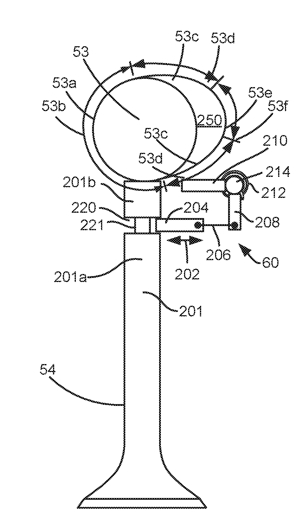
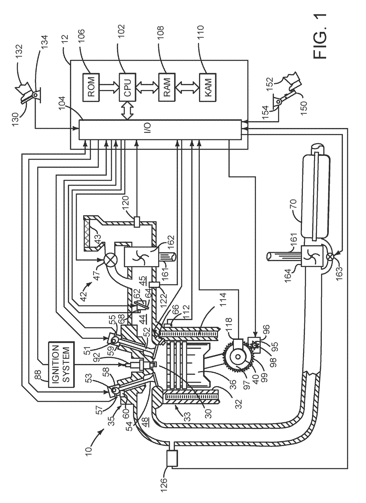
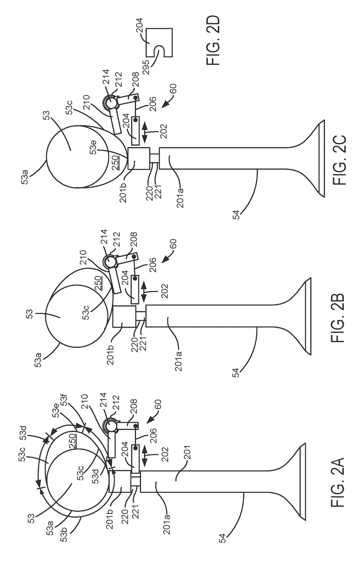
[0016]The present description is related to operating an internal combustion engine of a vehicle. Exhaust valves may be locked in a closed position to reduce the possibility of exhaust gas entering engine cylinders at undesirable times. The internal combustion engine may be configured as is shown in FIG. 1. The engine of FIG. 1 may include exhaust valves and exhaust valve locking mechanisms as is shown in FIGS. 2A-4C. The exhaust valve locking mechanism may operate according to the sequence shown in FIG. 5. The exhaust valve locking mechanism may be operated by the method of FIG. 6. The exhaust valve locking mechanism may be diagnosed according to the method of FIG. 7.

[0017]Referring to FIG. 1, internal combustion engine 10, comprising a plurality of cylinders, one cylinder of which is shown in FIG. 1, is controlled by electronic engine controller 12. Engine 10 is comprised of cylinder head 35 and block 33, which include combustion chamber 30 and cylinder walls 32. Piston 36 is posi...


PUM


Abstract

Systems and methods for operating exhaust valves of an internal combustion engine with poppet exhaust valves are described. The systems and methods provide for locking exhaust valves in a closed state when the exhaust valves are in mechanical communication with a base circle of a camshaft lobe. Locking the exhaust valves in a closed state may reduce the possibility of exhaust pressures opening the exhaust valves at times they may not be desired to be open.

Description

FIELD[0001]The present description relates to methods and a system for operating an exhaust valve of an internal combustion engine. The methods and systems may be particularly useful for engines that may operate with higher exhaust pressures.BACKGROUND AND SUMMARY[0002]An internal combustion engine inducts air to mix with fuel for combustion. Combusting the air and fuel raises pressure in engine cylinders which is translated into torque via engine pistons and a crankshaft. Exhaust gas exits the cylinders to make way for subsequent combustion events in the cylinder. The flow of exhaust gas from engine cylinders may be restricted by a catalyst or another device in the exhaust system such as a turbocharger turbine. At higher engine speeds and loads, pressure of exhaust gas in the exhaust manifold may be sufficiently high to cause closed exhaust valves to temporarily open. In particular, exhaust pressure acting on a back side of exhaust valves may be sufficient enough to overcome exhaus...

Claims


Application Information

Patent Timeline
Patent Type & Authority Applications(United States)
IPC IPC(8): F01L1/46
CPCF01L1/462F01L2800/14F01L2810/05F01L2800/11F01L2013/001F01L13/06F02D13/0242F02D13/06F02D2200/1015F01L2001/0537F01L2820/041F01L2820/042F01L1/46F01L3/24F01L2800/10
Inventor MARTIN, DOUGLAS RAYMONDROLLINGER, JOHN ERIC
Owner FORD GLOBAL TECH LLC
Why Eureka
Try Eureka