Split Cycle Engine and Method with Increased Power Density

a technology of power density and split cycle engine, which is applied in the direction of combustion engine, internal combustion piston engine, machine/engine, etc., can solve the problems of significant cost increase, significant cost increase, and added maintenance, and achieve significant cost or efficiency loss, increase the power density of the engine, and increase the effect of engine power outpu

Inactive Publication Date: 2011-12-15
ZAJAC OPTIMUM OUTPUT MOTORS
View PDF11 Cites 20 Cited by
  • Summary
  • Abstract
  • Description
  • Claims
  • Application Information

AI Technical Summary

Benefits of technology

[0008]It is, in general, an object of the invention to provide a new and improved internal combustion engine and method in which power density is increased without significant increases in cost or loss of efficiency.
[0009]Another object of the invention is to provide an engine and method of the above character which includes an inexpensive, regenerative hybrid system.
[0010]These and other objects are achieved in accordance with the invention by providing a split cycle engine and method in which air is compressed in a compression chamber, compressed air from the compression chamber is delivered to a combustion chamber where it is mixed with fuel in the combustion chamber to form a mixture which burns and expands, expanding gases from the combustion chamber are delivered to an expansion chamber to drive an output member, and the amount of air supplied to the compression chamber and, hence, the amount of air flowing through the rest of the engine is increased to increase the power output of the engine without a corresponding decrease in the efficiency of the engine.
[0011]In some embodiments, the pressure of the air delivered to the compression chamber is increased with a blower such as a supercharger or a turbocharger, and in others, the amount of air is increased by operating the engine in a hybrid mode in which the engine is operated in a braking mode as well as in a power mode. During the braking mode, air is drawn into the compression chamber, compressed, and stored in a pneumatic storage tank. During the power mode, compressed air from the storage tank is returned to the intake side of the compression chamber where it drives a compression piston during an intake stroke. The amount of air returned to the chamber can be controlled to make work done on the piston by the air either equal to or greater than the work done by the piston during a compression stroke.

Problems solved by technology

While such blowers can increase the pressure and power output of an engine, they also produce higher exhaust pressures which waste energy and often reduce the overall efficiency of the engine.
While hybrids can and do provide gains both in fuel efficiency and in power, these gains are offset by significant cost increases and added maintenance.
With electric hybrids, the system requires two complete drive systems, which means additional weight as well as increases in cost and maintenance.
Moreover, the cost and weight of the battery systems used in electric hybrids are substantial, and proper disposition of batteries that are worn out and no longer in use is a major concern.

Method used


Image

  • Split Cycle Engine and Method with Increased Power Density
  • Split Cycle Engine and Method with Increased Power Density
  • Split Cycle Engine and Method with Increased Power Density

Examples


Embodiment Construction

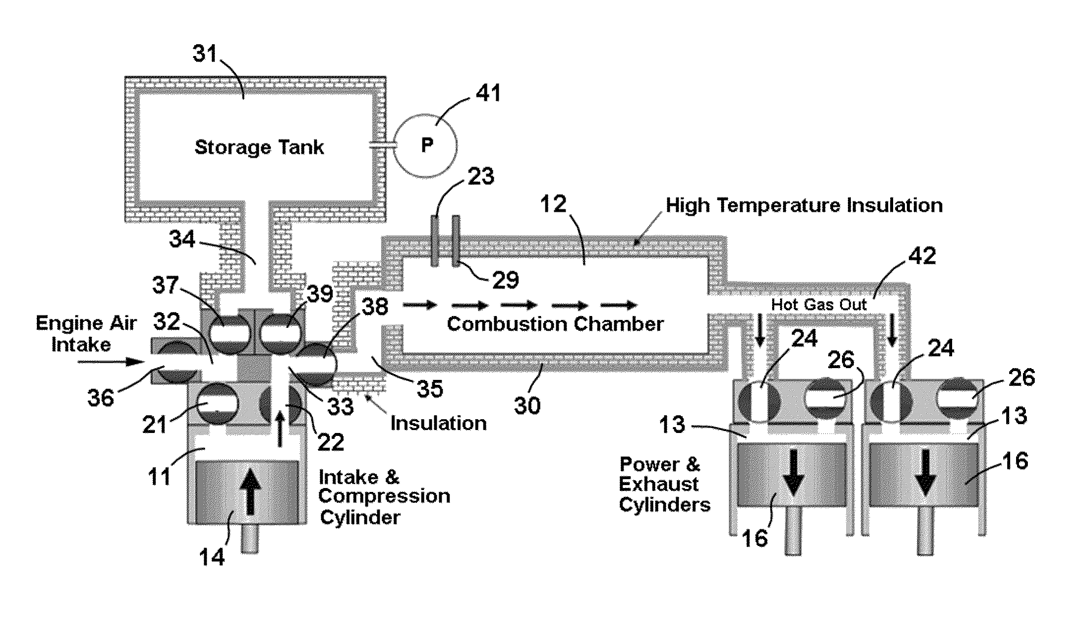
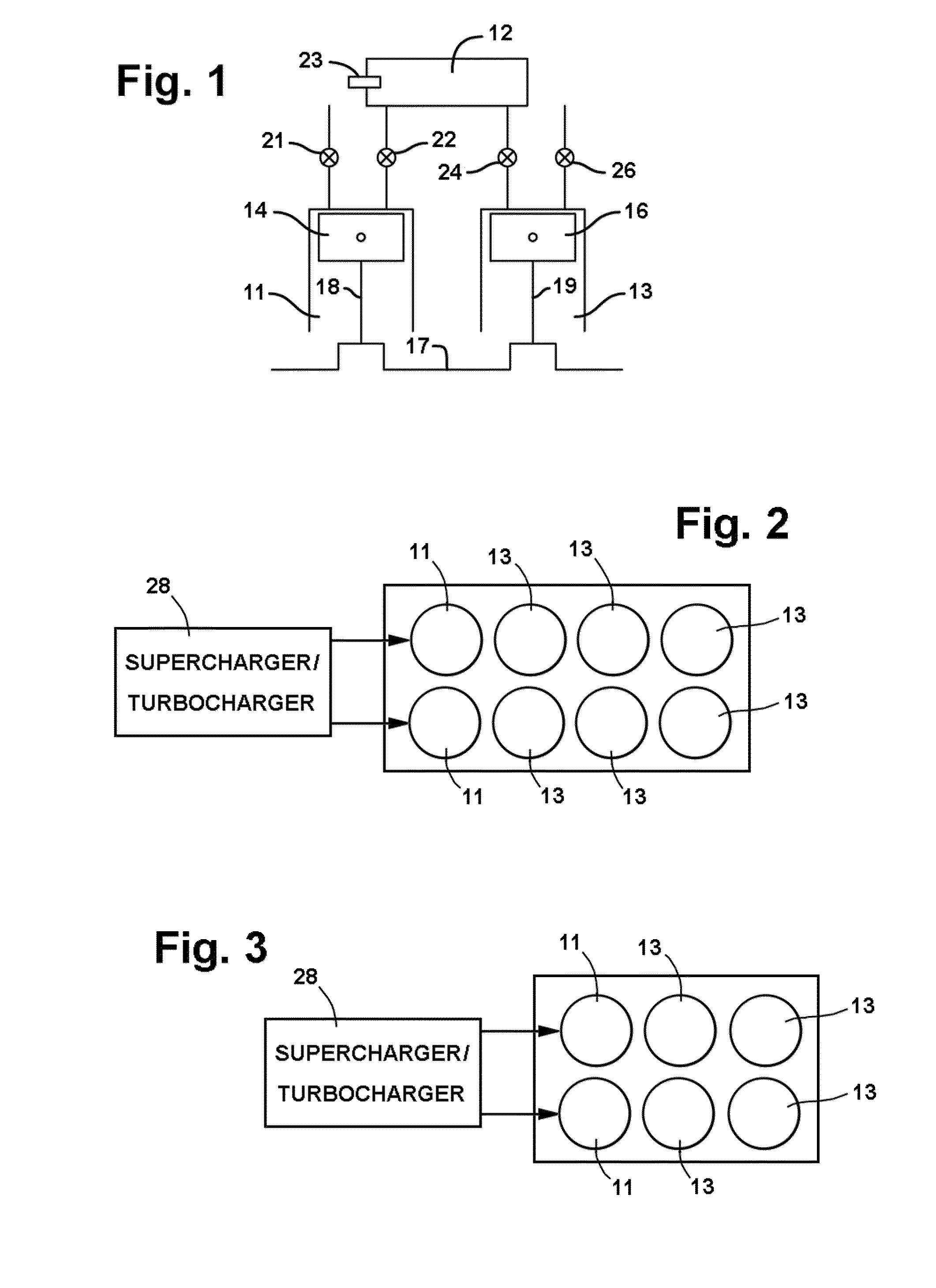
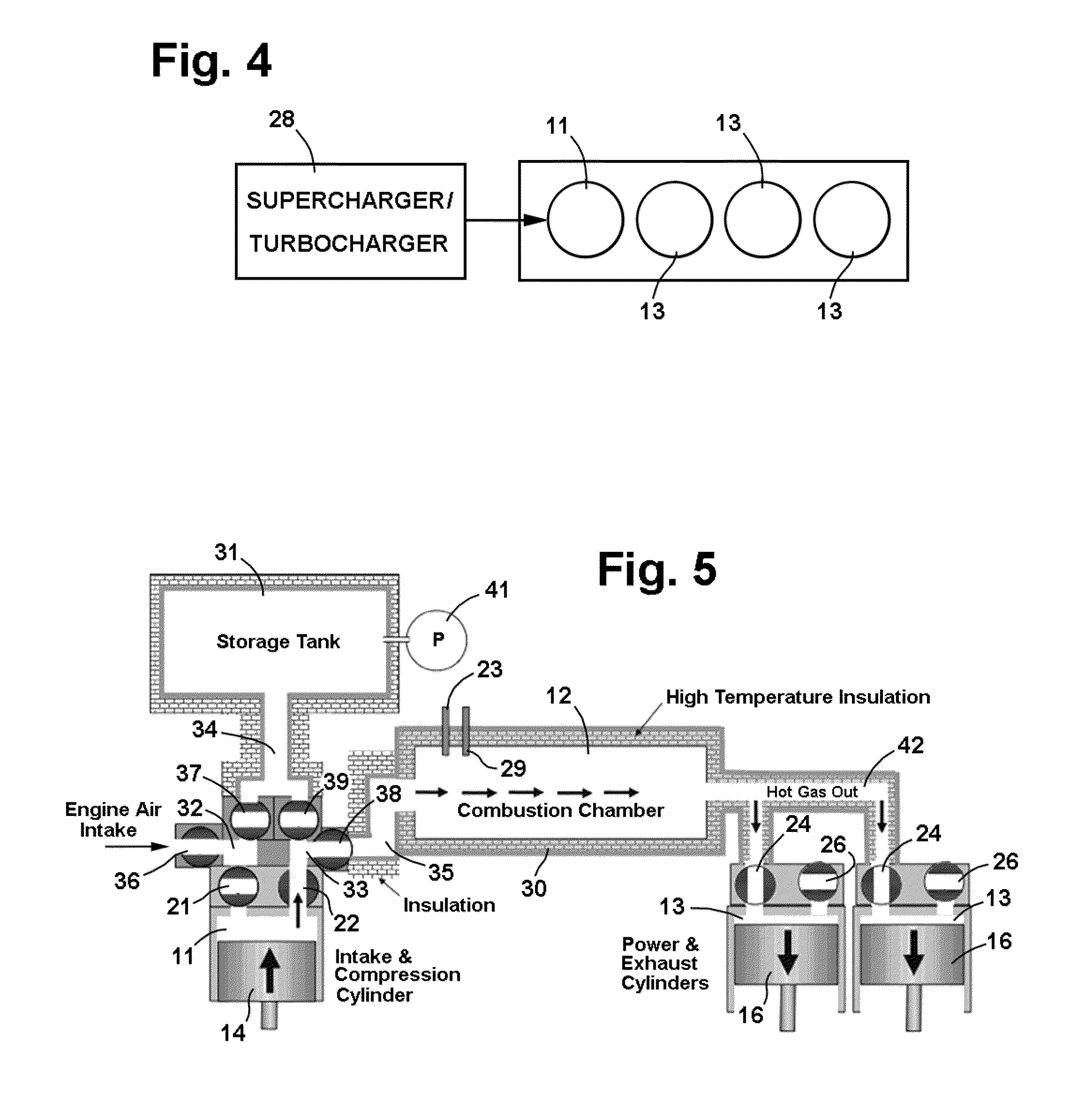
[0017]The split cycle engine illustrated in FIG. 1 has a compression cylinder 11, a combustion chamber 12, and an expansion cylinder 13, with reciprocating pistons 14, 16 in the compression and expansion cylinders forming chambers of variable volume. The pistons are connected to a crankshaft 17 by connecting rods 18, 19 for movement in concert between top dead center (TDC) and bottom dead center (BDC) positions in the cylinders, with each of the pistons making one upstroke and one downstroke during each revolution of the crankshaft.

[0018]Compression cylinder 11 receives fresh air through an intake valve 21 and communicates with the inlet end of combustion chamber 12 through an outlet valve 22. Fuel is injected into the combustion chamber through a fuel injector 23 or other suitable fuel inlet, where it is mixed with the air from the compression cylinder. The mixture burns and expands in the combustion chamber, and the expanding gas flows into the expansion cylinder from the outlet e...


PUM


Abstract

Split cycle engine and method in which output power and power density are increased in some embodiments with a turbocharger or supercharger which increases the pressure in the compression cylinder and also increases the power output of the engine without a corresponding decrease in the efficiency of the engine (work done per unit fuel). In other embodiments, the engine is used for braking, and the energy produced by braking is stored pneumatically and then used in driving the compressor.

Description

RELATED APPLICATIONS[0001]Provisional Application No. 61 / 353,572, filed Jun. 10, 2010, the priority of which is claimed.BACKGROUND OF THE INVENTION[0002]1. Field of Invention[0003]This invention pertains generally to internal combustion engines and, more particularly, to a split cycle engine and method in which the power output and power density (HP / cu-in displacement) are increased without significantly reducing fuel efficiency.[0004]2. Related Art[0005]Heretofore, superchargers and turbochargers have been utilized in the air intake systems of internal combustion engines. While such blowers can increase the pressure and power output of an engine, they also produce higher exhaust pressures which waste energy and often reduce the overall efficiency of the engine.[0006]Another way to increase power with an internal combustion engine is to add a replenishable power system, as is currently done in hybrid vehicles where electric motors supplement the internal combustion engines. The effi...

Claims


Application Information

Patent Timeline
Patent Type & Authority Applications(United States)
IPC IPC(8): F02B19/14
CPCF02B41/06F02B41/02Y02T10/42Y02T10/40
Inventor ZAJAC, JOHNMORAN, JOSEPH
Owner ZAJAC OPTIMUM OUTPUT MOTORS
Why Eureka
Try Eureka