Multi-link engine

a multi-link engine and engine technology, applied in the direction of connecting rods, bearings, shafts and bearings, etc., can solve the problems of degraded fuel efficiency of the engine, increased cost, and second-order vibration, so as to reduce second-order vibration, reduce cost, and reduce the effect of degraded fuel efficiency

Active Publication Date: 2011-08-11
NISSAN MOTOR CO LTD
View PDF6 Cites 7 Cited by
  • Summary
  • Abstract
  • Description
  • Claims
  • Application Information

AI Technical Summary

Benefits of technology

[0009]The multi-link engine disclosed in the aforementioned patent publication has a second order balancer device provided below the crankshaft. The second order balancer device reduces second order vibrations in a direction oriented diagonally with respect to a piston movement direction by rotating a first balancer shaft and a second balancer shaft in a direction opposite to the rotational direction of the crankshaft. However, with the multi-link engine presented in the aforementioned patent publication, the cost is increased by the need to provide a separate second order balancer device and the fuel efficiency of the engine is degraded due to friction generated when the second order balancer device is driven.
[0010]The present invention was conceived in view of these problems. One object is to provide a simple vibration reducing structure for a multi-link engine that can reduce vibrations in a transversely oriented direction with respect to a piston movement direction.

Problems solved by technology

The second order vibration problem is unique to multi-link engines.
However, with the multi-link engine presented in the aforementioned patent publication, the cost is increased by the need to provide a separate second order balancer device and the fuel efficiency of the engine is degraded due to friction generated when the second order balancer device is driven.

Method used


Image

  • Multi-link engine
  • Multi-link engine
  • Multi-link engine

Examples


second embodiment

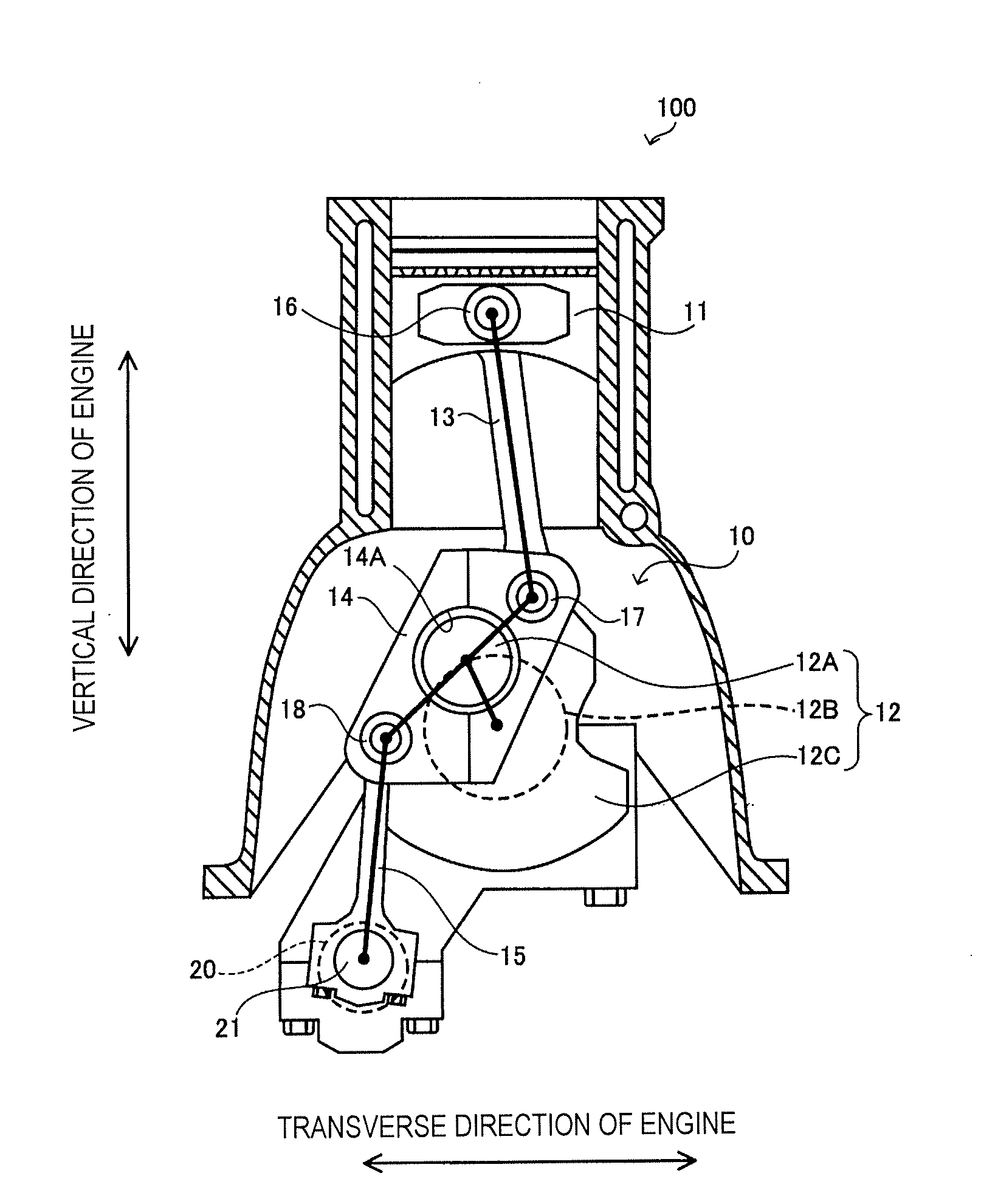
[0076]Referring now to FIGS. 7A to 7C, the links 13, 14 and 15 of the multi-link engine 100 according to a second embodiment will now be explained. FIG. 7A shows the lower link 14. FIG. 7B shows the upper link 13. FIG. 7C shows the control link 15. The constituent features of a multi-link engine 100 according to the second embodiment are the same as in the first embodiment, except that the lower link 14 is configured differently. In view of the similarity between the first and second embodiments, only difference between the lower link 14 of the first and second embodiments will be explained. In other words, the descriptions of the parts of the second embodiment that are identical to the parts of the first embodiment have been omitted for the sake of brevity.

[0077]As shown in FIG. 7A, the coupling hole 14A is configured and arranged such that the center axis of the crankpin 12A will be arranged between the center axis of the upper pin 17 and the center axis of the control pin 18 on a...

third embodiment

[0086]A multi-link engine 100 according to a third embodiment will now be explained with reference to FIGS. 8 and 9. FIG. 8 is a schematic view of a multi-link engine 100 according to the third embodiment. FIG. 9 shows the transversely oriented second order inertia forces acting at the centers of gravity of the links of the multi-link engine 100. The multi-link engine 100 according to the third embodiment is basically the same as the first embodiment in that the links are configured to satisfy the equation (12). However, the control link 15 is configured differently. Specifically, in this embodiment, a counterweight 15B is provided on the control link 15. The third embodiment will now be explained focusing on this difference.

[0087]As shown in the equation (11), among the second order and higher order inertia forces oriented in a transverse direction of the engine, the inertia forces acting on the lower link 14 and the control link 15 are oriented in the same direction (thus, both ar...

fourth embodiment

[0095]A multi-link engine 100 according to a fourth embodiment will now be explained with reference to FIGS. 10A, 10B, 11A and 11B. FIG. 10A is schematic view of the multi-link engine 100 according to a fourth embodiment. FIG. 10B is a schematic view of a control link 15. FIG. 11A is a plot illustrating second order inertia forces acting on the links in a transverse direction of the engine. FIG. 11B is a plot illustrating second order inertia forces acting on the links in a vertical direction of the engine (piston movement direction). The constituent features of the multi-link engine 100 according to the fourth embodiment are the same as in the third embodiment, except that the position of the center of gravity of the control link 15 is different. Specifically, the control link 15 is provided with a counterweight 15B contrived such that the center of gravity Gc of the control link 15 is offset from a line passing through the center axis of the control pin 18 and the center axis of t...


PUM


Abstract

A multi-link engine is provided with an upper link, a lower link and a control link. The upper link is pivotally connected to a piston by a piston pin. The lower link is rotatably mounted on a crankpin of a crankshaft and connected to the upper link by an upper pin. The control link is rotatably connected to the lower link by a control pin and pivotally mounted on a pivot portion of a control shaft. The links are configured and arranged with respect to each other such that inertia forces of a prescribed second or higher order in terms of an engine rotational speed act on at least the upper link and the control link in a transverse direction of the engine with a sum of leftward and rightward inertia forces of the prescribed second or higher order being substantially zero.

Description

CROSS-REFERENCE TO RELATED APPLICATIONS[0001]This application claims priority to Japanese Patent Application No. 2008-270149, filed on Oct. 20, 2008. The entire disclosure of Japanese Patent Application No. 2008-270149 is hereby incorporated herein by reference.BACKGROUND OF THE INVENTION[0002]1. Field of the Invention[0003]The present invention generally relates to a multi-link engine. More specifically, the present invention relates to a vibration reducing structure that reduces vibration in a multi-link engine.[0004]2. Background Information[0005]Engines have been developed in which a piston pin and a crank pin are connected by a plurality of links (such engines are hereinafter called multi-link engines). For example, a multi-link engine is disclosed in Japanese Laid-Open Patent Publication No. 2006-207634. The multi-link engine of this patent publication is provided with an upper link and a lower link for connecting a piston to a crankshaft. The upper link is connected to a pist...

Claims


Application Information

Patent Timeline
Patent Type & Authority Applications(United States)
IPC IPC(8): F02B75/32
CPCF02B75/06F02B75/048F16F15/24F02B75/04F02B75/32
Inventor SATOU, YUUSUKE
Owner NISSAN MOTOR CO LTD
Why Eureka
Try Eureka