Container closure assembly

a container and assembly technology, applied in the direction of liquid handling, caps, applications, etc., can solve the problems of high removal torque, high standard deviation of removal torque, high force for elderly users, etc., and achieve the effect of easy opening of containers

Inactive Publication Date: 2008-06-26
ABBOTT LAB INC
View PDF9 Cites 24 Cited by
  • Summary
  • Abstract
  • Description
  • Claims
  • Application Information

AI Technical Summary

Benefits of technology

[0018]A continuous retaining bead on the container located slightly above the sloping teeth of the closure is also included. As removal torque is applied to the closure, the closure rides upward on the thread(s) on the neck of the container while the sloping teeth on the closure are grabbed under this bead, thereby bringing about a gradual stretching of the rupturable bridges and subsequent breakage of the rupturable bridges to separate the tamper-indicating band from the side wall of the closure. The closure / container assembly described herein can provide removal torques between approximately 3 and 16 inch pounds on average, thereby enabling elderly users and arthritic users to open the container with ease.

Problems solved by technology

The locking mechanism requires the force to remove the cap and to break the band to be applied simultaneously, thereby resulting in high removal torques and high standard deviations of removal torque.
This force is too high for elderly users and users suffering from arthritis.
Accordingly, the closure is subject to back-off and possible leakage during distribution.
This type of closure also does not provide any audible feedback in the area between cap opening and band breakage to reassure the consumer of safety.
U.S. Pat. No. 4,991,731 describes problems encountered when packaging consumable products in sealed containers.
A problem arises when attempting to provide a cap for a plastic container, wherein the cap maintains a hermetic seal.
Because it is difficult to maintain a hermetic seal in a plastic container, and conventional metal caps and plastic containers expand by a dissimilar amount, metal caps, by themselves, do not maintain a hermetic seals consistently on plastic containers when subjected to retort conditions.
During retort conditions, heat causes polymer relaxation or shrinkage, especially in the upper neck portion of the container.
This shrinkage causes severe problems in maintaining a conventional metal cap on a plastic bottle.
However, the amount of torque necessary to maintain a conventional cap on a plastic bottle is so high that a person would not be able to easily twist the cap off the bottle following retort.
Screw on bottle caps have a tendency to loosen from a tightened condition on a threaded bottle neck finish.
This tendency to loosen has a number of causes, including, for example, temperature change, creep in the bottle and cap materials, relaxation of a liner or sealant material, and vibration during handling and shipping.
This problem is more frequently encountered when the screw threads have a high pitch to enable the cap to be quickly removed and reinstalled with limited twisting action.
Loose caps create problems for the manufacturer and retailer of packaged goods and even for the ultimate user.
A good moisture seal is especially important, for example, when pharmaceuticals and dietary supplements can be adversely affected by excess increases of or by excess decreases of moisture content.
While “anti-back off” features are known in the industry, these features have not generally been available for bottles intended for use by elderly persons having limited strength and by sufferers from arthritis.

Method used


Image

  • Container closure assembly
  • Container closure assembly
  • Container closure assembly

Examples


Embodiment Construction

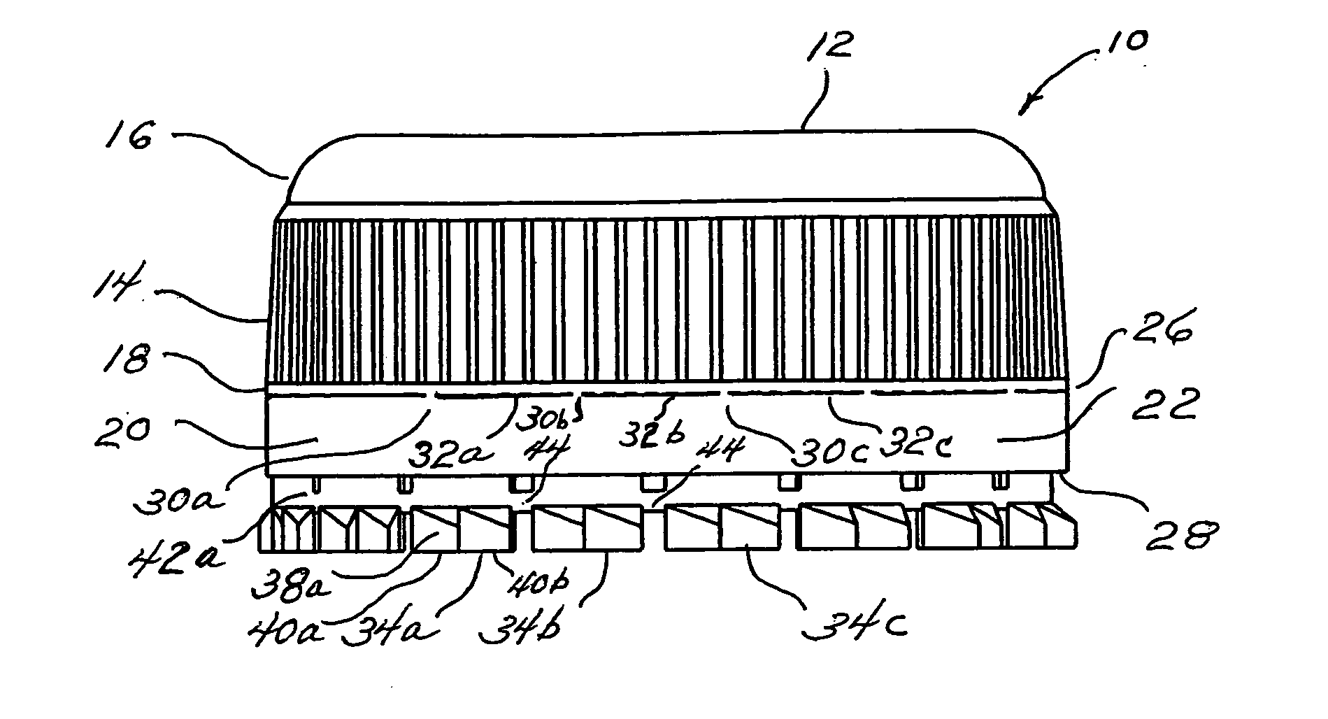
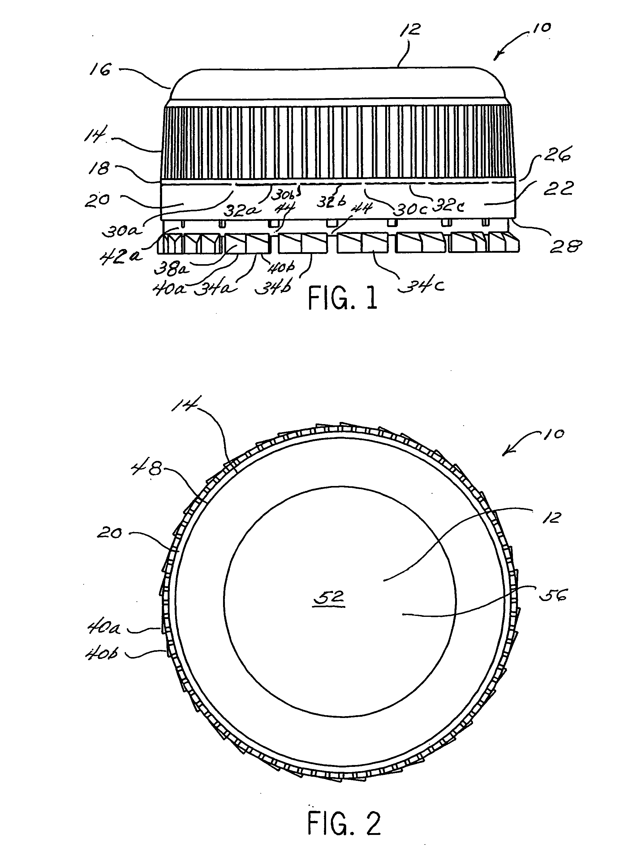
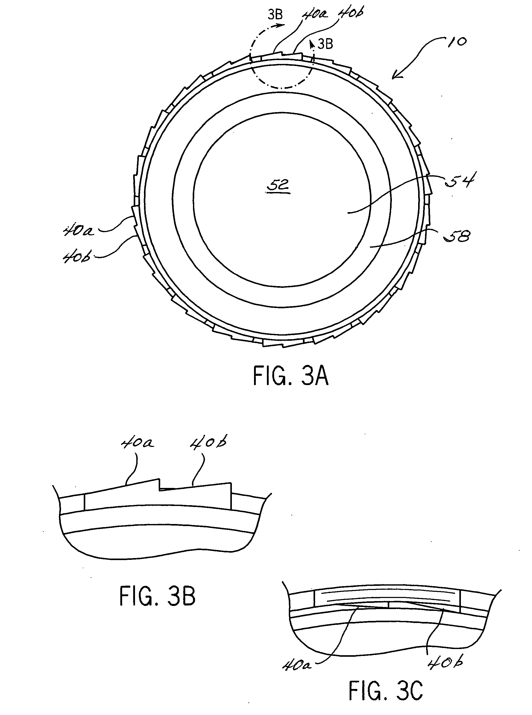
[0029]As used herein term “side wall” means that portion of a closure depending from the top wall of the closure. The term “side wall” is synonymous with the term “skirt.” As used herein, the expression “top wall” means a panel that covers the opening of the closure that is positioned distally from the neck of the container. The expression “top wall” is synonymous with the expressions “end wall”, “cover”, “end panel”, “upper portion”. As used herein, the term “tooth” means a projecting part resembling a tooth, as on a saw. The expression “sloping tooth” is synonymous with the term “ratchet.” As used herein, the expression “closure / container assembly” means a combination of the closure and the container to make a completed product. As used herein, the term “closure” means an object that closes the mouth of a container. As used herein, the term “container” means a receptacle for holding or carrying a material. As used herein, the term “etc.” is indicative of a situation in which compo...


PUM


Abstract

An assembly comprising a container and a closure. The container has a neck, the neck having an interior surface and an exterior surface, the exterior surface having (a) a thread(s), (b) at least two sets of sloping teeth. The closure has (a) a top wall; (b) a side wall having an interior surface, an exterior surface, an upper portion, and a lower portion; (c) a thread(s) on the interior surface of the side wall; (d) a tamper-indicating band having an interior surface, an exterior surface, an upper edge, and a lower edge, the upper edge of said tamper indicating band attached to the lower portion of the side wall by a plurality of rupturable bridges; and (e) a plurality of tabs attached to the lower edge of the tamper-indicating band, each of the tabs having an interior surface and an exterior surface, the exterior surface of each of the tabs bearing at least one sloping tooth, each of the tabs being foldable to contact the interior surface of the tamper-indicating band, whereby, when folded, the at least one sloping tooth on each tab faces toward the axis of the side wall. When the tabs are folded, the sloping teeth on the tabs of the closure, partially engage with the sloping teeth on the exterior surface of the neck of the container.

Description

BACKGROUND OF THE INVENTION[0001]1. Field of the Invention[0002]This invention provides an easy to open container / closure assembly, more particularly, an easy to open closure / container assembly having a tamper-indicating feature.[0003]2. Discussion of the Art[0004]Two main types of bottle / closure systems that utilize breakaway bands for indicating tampering are currently commercially available. Both types have certain drawbacks. The first type locks the tamper-indicating band in place. The locking mechanism requires the force to remove the cap and to break the band to be applied simultaneously, thereby resulting in high removal torques and high standard deviations of removal torque. The lowest removal torque that can be achieved with this system is approximately 18 inch pounds on average. This force is too high for elderly users and users suffering from arthritis. The second type involves the separation of the opening force from the force required to remove the tamper-indicating ban...

Claims


Application Information

Patent Timeline
Patent Type & Authority Applications(United States)
IPC IPC(8): B65D41/02
CPCB65D41/3428B65D41/3409
Inventor LOUGHRIN, THOMAS D.ROGERS, KRISTI L.STOKESBURY, ELWOOD L.
Owner ABBOTT LAB INC
Why Eureka
Try Eureka