Deployment brake release for a parachute

a technology of deployment brake and parachute, which is applied in the field of deployment brake release system, can solve the problems of increasing cost and weight, adding unnecessary complexity and expense, and pyrotechnic devices that require proper timing, and achieves the effects of simple deployment, low cost and light weigh

Active Publication Date: 2008-06-26
AIRBORN SYST NORTH AMERICA OF NJ INC
View PDF19 Cites 23 Cited by
  • Summary
  • Abstract
  • Description
  • Claims
  • Application Information

AI Technical Summary

Benefits of technology

[0012]It is therefore an object of the present invention to provide a deployment brake release system in which the AGU motor is not subjected to opening force loads, thus enabling motors of lower cost and lighter weight to be used.
[0013]Another object of the present invention is to provide a deployment brake release system for use with UAVs that supports simultaneous or sequential release of multiple brake lines.
[0014]A further object of the present invention is to provide a relatively simple deployment brake release system for use with UAVs that employs hook mounts on the AGU frame that are fully reusable.
[0015]A still further object of the present invention is to provide a deployment brake release system for use with UAVs which is both reliable and secure in use and easy to rig, with minimal opportunities for snagging hazard.
[0016]Yet another object of the present invention is to provide a deployment brake release system that can be readily adapted to fit and work effectively with a wide range of UAV parachute sizes and styles without requiring adaptation of the existing parachute structure.
[0017]It is yet another object of the invention to provide a deployment brake release system for UAVs that is not complex in structure and which will conform to conventional forms of manufacture so as to provide a brake release system that is economically feasible, long-lasting and relatively trouble free in operation.

Problems solved by technology

To withstand the peak load, the motor attached to the brake / suspension lines must be relatively heavy duty which increases cost and weight, both of which are undesirable characteristics in parachute product design.
While this can be effective, pyrotechnic devices require proper timing and add unwanted complexity and expense, particularly in the context of routine and repeated airborne delivery of equipment and supplies such as is needed for troop support during military operations.

Method used


Image

  • Deployment brake release for a parachute
  • Deployment brake release for a parachute
  • Deployment brake release for a parachute

Examples


first embodiment

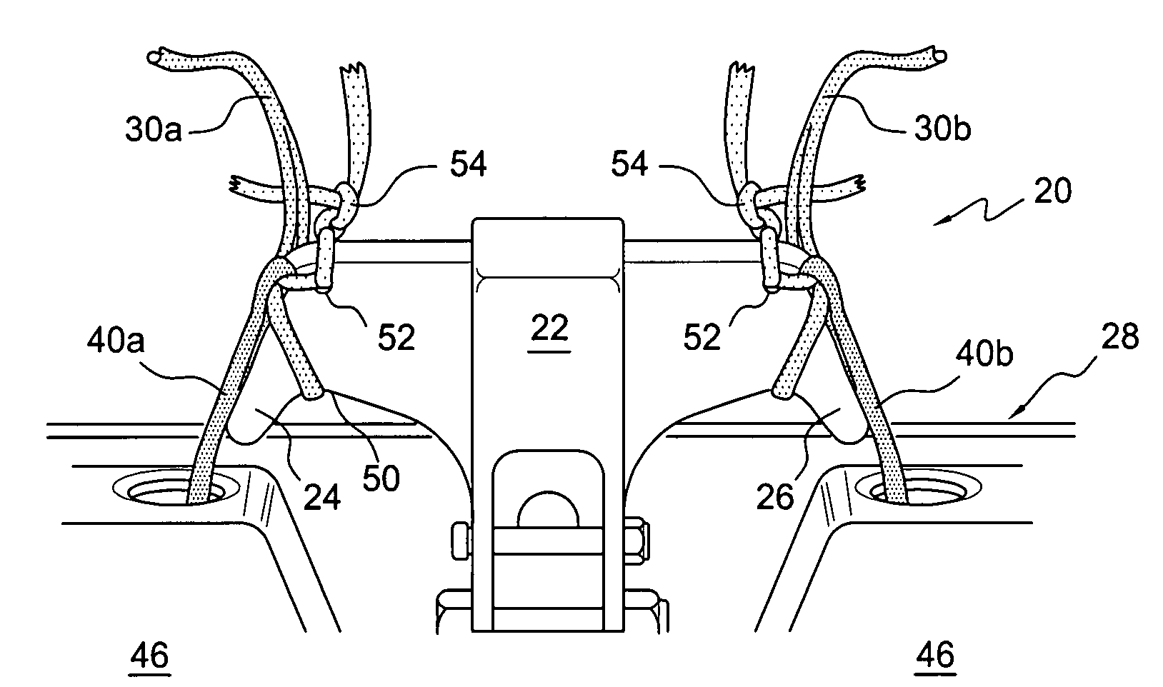
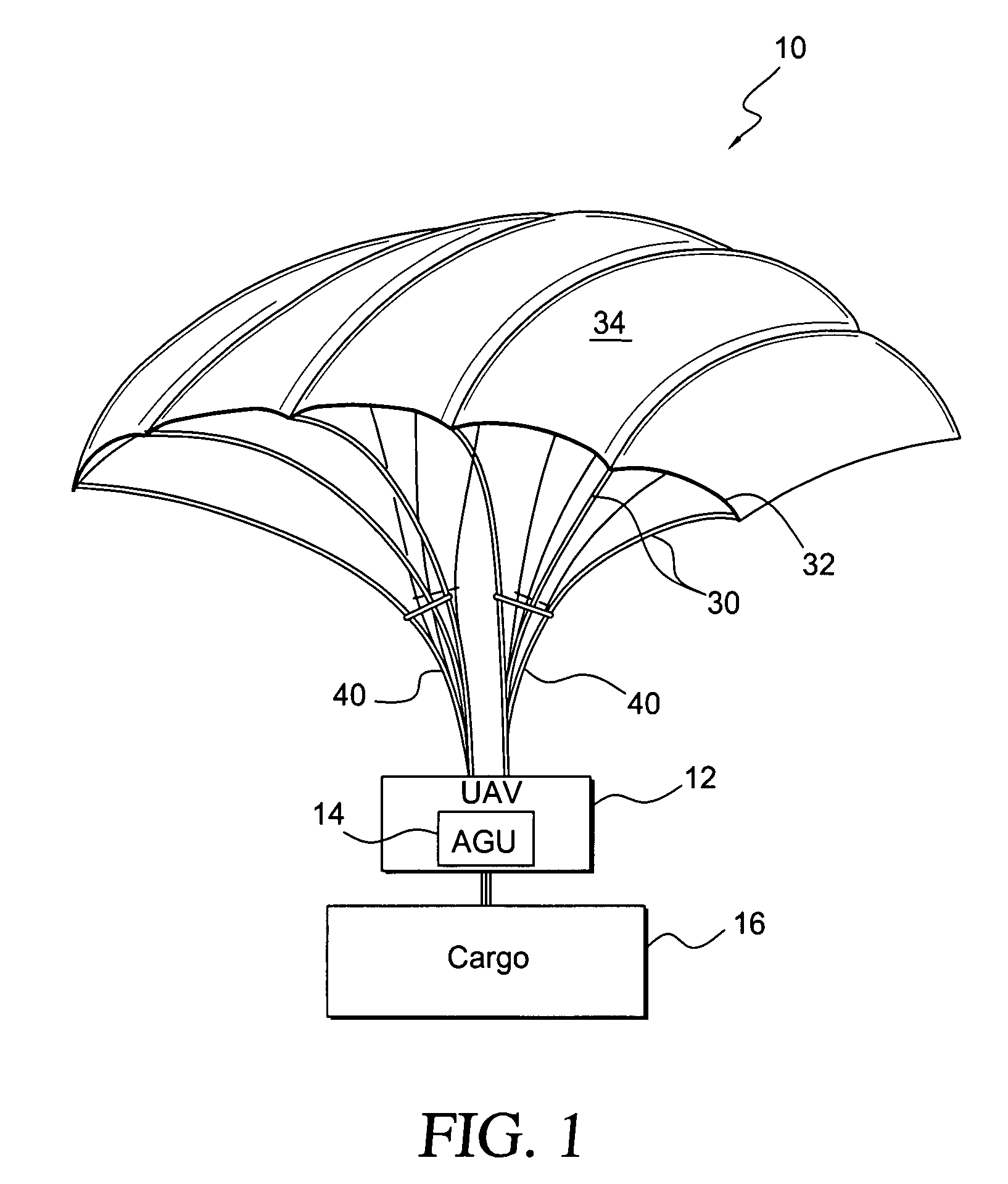
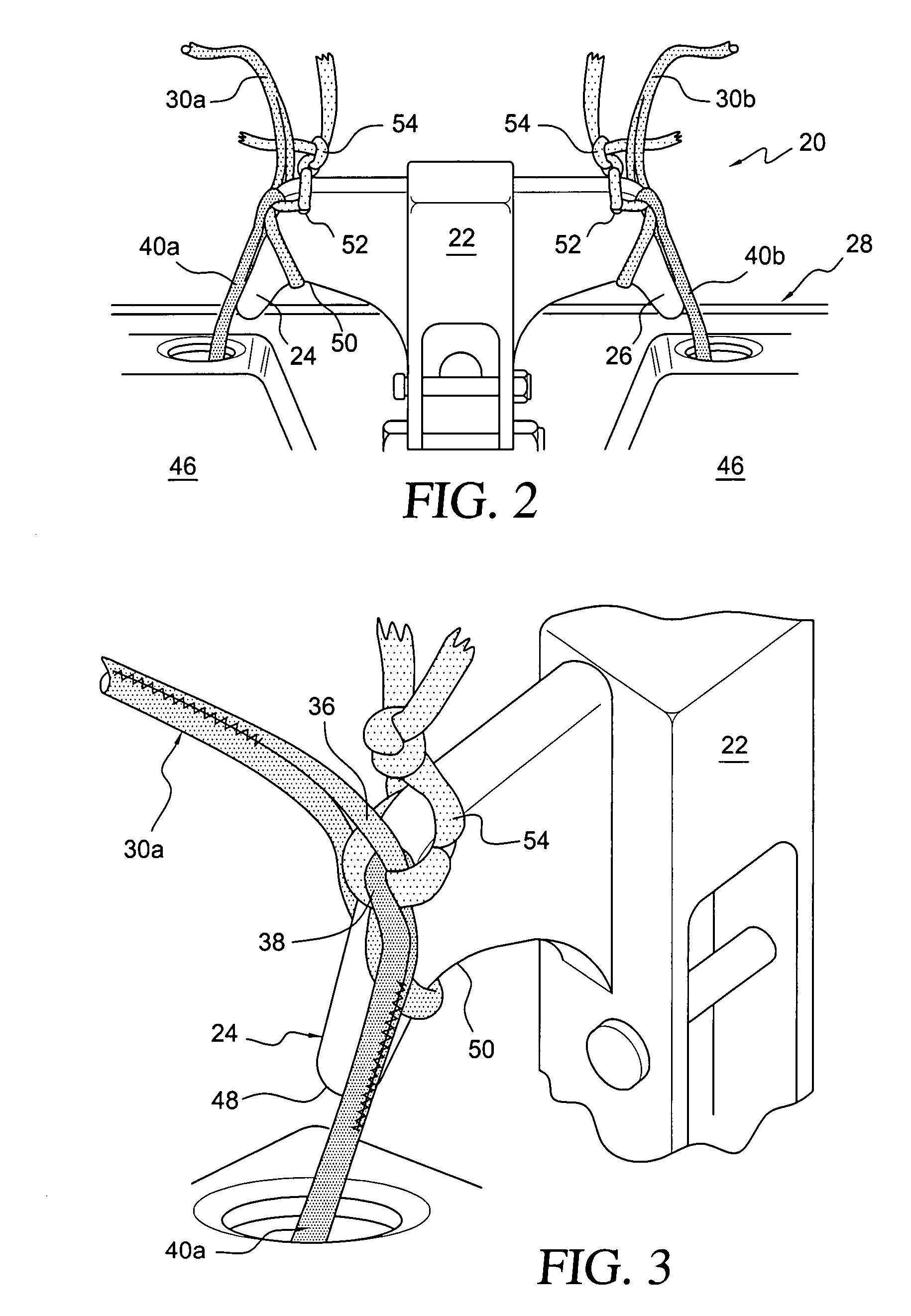
[0034]the present invention is shown in FIGS. 2 and 3. A deployment brake release system, generally designated by the reference numeral 20, is mounted on the rear of AGU 14 of a parachute system 10 such as that shown in FIG. 1. Shown in FIGS. 2 and 3 in a rigged, pre-deployment configuration, the deployment brake release system 20 includes a hook mount 22 having first and second hooks 22, 24 respectively mounted on the left and right sides of the frame 28 of the AGU. While the preferred embodiment includes left and right hooks, it is possible to construct the deployment brake release system with only a single hook.

[0035]As is known, deployment brake release lines 30 are attached to the trailing edge 32 of a parachute canopy 34 during rigging to effect downward deflection of the edge 32 during initial inflation. The deployment brake release lines 30 are subsequently released to allow full inflation of the chute at the appropriate time and, in the case of the left and right outer brak...

second embodiment

[0041]the present invention especially useful for larger cargo parachute systems is shown in FIG. 4. Larger cargo parachute systems need additional brake lines to accommodate the greater total force on the canopy trailing edge and to maintain a better trim shape of the canopy control surfaces during deployment. In most cases, these additional brake lines are used to deflect the canopy only during deployment; they are not used to steer the parachute once steady state flight status has been achieved. Thus, while the release of a greater number of brake lines is required, generally only the last brake line released on each side, i.e., the outer brake lines, will ultimately act as steering brake lines to be controlled by the motors.

[0042]In the embodiment shown in FIG. 4, there is only one additional brake line on each side. (The third line shown is a so-called “lazy line” to be described later.) Hence, there are left inner and outer brake lines 60 and 62, respectively, and right inner ...


PUM


Abstract

A deployment brake release system for use with an airborne guidance unit (AGU) of a parachute suitable for precision cargo delivery. The parachute includes deployment brake lines secured at one end to the edge of the canopy and connected at the other end through looped ends to motor control lines. The motor control lines are, in turn, engaged with the motor of the AGU. The deployment brake release system includes at least one hook mount having a hook secured to the AGU frame. The looped ends of the deployment brake lines are engaged with the hook during rigging so that, upon deployment, opening forces are applied to the hook mount rather than the motor. After full canopy inflation, the motor, via the motor control lines, pulls on the brake line looped ends to disengage them from the hook, transferring subsequent canopy loads to the AGU motor for the remainder of the flight. A method for releasing the deployment brake lines is also disclosed.

Description

BACKGROUND OF THE INVENTION[0001]1. Field of the Invention[0002]The present invention relates in general to deployment brakes operative during the opening of parachute canopies and, more particularly, to a deployment brake release system that is configurable for use with canopies of different types and sizes.[0003]2. Description of the Related Art[0004]Precision cargo delivery relies upon unmanned aerial vehicles (UAVs) to guide cargo parachutes to preselected GPS coordinates. The UAV includes an airborne guidance unit (AGU) having a structural frame that contains at least one battery, a motor, an avionics computer with GPS receiver, a motor controller, a processor, etc. A compass or other rate sensing instrument may also be included.[0005]The precision cargo delivery parachute systems are similar to those used in personnel parachutes and can include low gliding round parachutes and higher gliding ram-air parachutes, as well as cruciform parachutes of the type disclosed in U.S. Pat....

Claims


Application Information

Patent Timeline
Patent Type & Authority Applications(United States)
IPC IPC(8): B64D17/62
CPCB64C39/024B64C2201/105B64C2201/107B64D17/62B64C2201/145B64D17/34B64C2201/128B64U30/12B64U10/50B64U2101/60B64U2201/104
Inventor DUNKER, STORMGILBERT, MARTIN
Owner AIRBORN SYST NORTH AMERICA OF NJ INC
Why Eureka
Try Eureka