Apparatus and Method for Angle-Resolved Determination of the Distance and Speed of an Object

a technology of angle resolution and distance, applied in the field of angle resolution determination of distance and speed of objects, can solve the problems of limiting the application field of sensors, large losses in the requisite distributor network, and high output power required of transmitting devices, etc., and achieves short measurement times and low power losses.

Inactive Publication Date: 2008-06-26
ROBERT BOSCH GMBH
View PDF21 Cites 221 Cited by
  • Summary
  • Abstract
  • Description
  • Claims
  • Application Information

AI Technical Summary

Benefits of technology

[0013]Example embodiments of the present invention provide an apparatus and a method that make possible short measurement times, that exhibit low power losses, and that dispense with one of the transmitting and receiving devices at the high-frequency level (77 / 122 / 140 GHz; see above).

Problems solved by technology

The achievable angular resolution, as well as the angle range covered, are disadvantageously defined by the mechanical configuration, and thus limit the field of application of the sensor.
A disadvantage of this assemblage is that a high output power is required for the transmitting device, since part of the transmitted signal must be made available, for all receiving directions, for a receiving mixer, and large losses in the requisite distributor networks occur because of the strong damping in the frequencies used, in the region of 76-81, 122-123, or 126-150 GHz (or even higher).
The disadvantage of this apparatus is that the duration of a measurement using all the antenna devices is too long, because of the multiplexing method, to allow this apparatus to be used for dynamic situations in road traffic.
This apparatus likewise has the disadvantage of too long a measurement time.

Method used


Image

  • Apparatus and Method for Angle-Resolved Determination of the Distance and Speed of an Object
  • Apparatus and Method for Angle-Resolved Determination of the Distance and Speed of an Object
  • Apparatus and Method for Angle-Resolved Determination of the Distance and Speed of an Object

Examples


Embodiment Construction

[0040]In the Figures, identical reference characters designate identical or functionally identical components, provided nothing to the contrary is indicated.

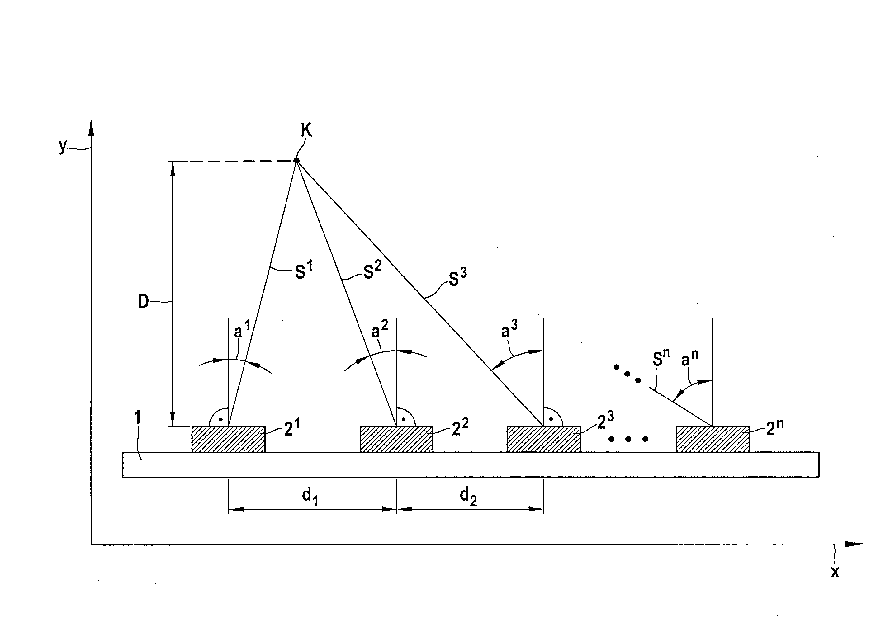
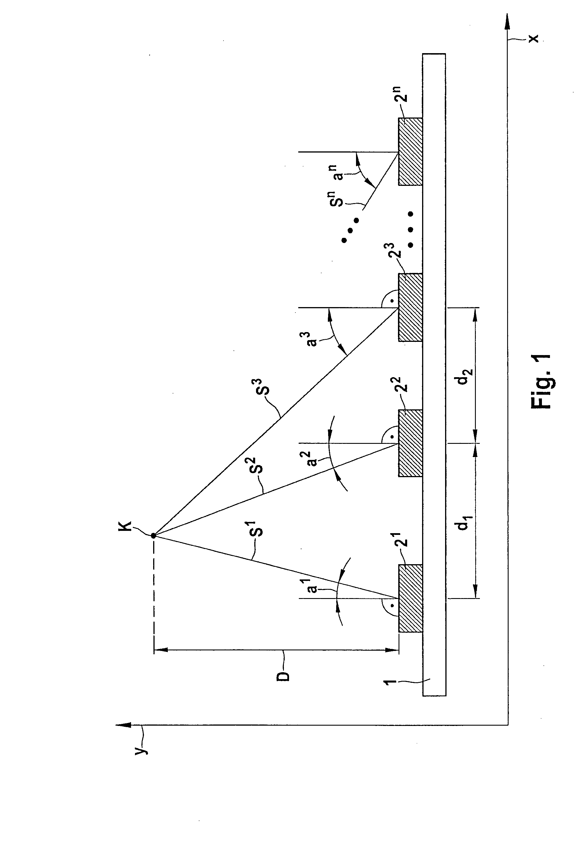
[0041]FIG. 1 is a schematic depiction of an example embodiment of the present invention, in a side view. A plurality of sensor modules 21, 22, 23, 2n are disposed on a carrier 1. This carrier 1 can, for example, be mounted on a surface on a front side of a vehicle. In the embodiment depicted, sensor modules 21, 22, 23, 2n are disposed along a spatial direction x at spacings d1, d2. Spacings d1, d2 can be in the range from 1 mm to 4 cm. An object K is located, in a spatial direction y orthogonal to direction x, for example in the direction of travel of the vehicle, at an object distance D with respect to sensor modules 21, 22, 23, 2n. Travel pathways 21, 22, 23, 2n between transmitting modules 21, 22, 23, 2n and object K are generally of different lengths. Travel pathways S1, S2, S3, Sn extend with respect to direction y at angle...


PUM


Abstract

An apparatus includes a plurality of sensor modules that are disposed at spacings with respect to one another, each sensor module having a local oscillator device. The oscillator device generates an oscillator signal that is passed on to a transmit/receive device, and the oscillator signal is radiated. The transmit/receive device is set up such that it can receive signals reflected from the object. A phase detection device is coupled at one input to the oscillator device and at a second input to the transmit/receive device. Based on the oscillator signal and the received reflected signals, the phase detection device determines a phase signal. A control and signal-processing device determines, based on the spacings of the sensor modules with respect to one another and the phase signals, a direction of the object with respect to the sensor module.

Description

FIELD OF THE INVENTION[0001]The present invention relates to an apparatus for determining a direction to an object, and to a method for directional determination using the apparatus.[0002]Although example embodiments of the present invention are described with reference to radar systems in vehicles, the present invention is not limited thereto.BACKGROUND INFORMATION[0003]U.S. Patent Application Publication No. 2002 / 0147534 describes an object sensing system having a plurality of FCWM sensors that determine the position of the object by triangulation. The same thing is described in U.S. Pat. No. 5,872,536. PCT International Published Patent Application No. WO 00 / 08484 describes a parking aid having a plurality of ultrasonic distance sensors. The latter are operated at different transmitting frequencies and are equipped with bandpass filters to prevent superimposition of the signals.[0004]U.S. Patent Application Publication No. 2002 / 0075178 describes an FCWM radar transmitter having a...

Claims


Application Information

Patent Timeline
Patent Type & Authority Applications(United States)
IPC IPC(8): G01S13/08G01S13/931
CPCG01S13/003G01S13/345G01S13/48G01S2013/9375G01S13/87G01S13/931G01S13/584G01S2013/93271G01S7/0232G01S7/0235
Inventor VOIGTLAENDER, KLAUSIRION, HANSSTEINHAUER, MATHIASMENZEL, WOLFGANG
Owner ROBERT BOSCH GMBH
Why Eureka
Try Eureka