Image forming method and image forming apparatus

a technology of image forming and nozzle, which is applied in the direction of printing, other printing apparatus, etc., can solve the problems of band-shaped non-uniformities in the resulting image, non-uniform effective nozzle pitch, and inability to achieve uniform effective nozzle pitch, so as to reduce the band-shaped non-uniformity and reduce the distance between the dots.

Inactive Publication Date: 2008-06-26
FUJIFILM CORP
View PDF5 Cites 7 Cited by
  • Summary
  • Abstract
  • Description
  • Claims
  • Application Information

AI Technical Summary

Benefits of technology

[0013]According to the present invention, even in a situation where the positions of dots formed by droplets ejected from the main nozzles diverge from the standard positions due to inclination of the recording head, and hence there is variation in the distance between the dots created by the main nozzles, which may cause visible band-shaped non-uniformity, droplet ejection is performed by using subsidiary nozzles which are able to form dots in positions where the variation in the distance between the dots is reduced, instead of using the main nozzles, and therefore it is possible to reduce the band-shaped non-uniformity.

Problems solved by technology

Therefore, if a recording head having a nozzle arrangement of this kind is installed at an oblique inclination with respect to the prescribed installation position (the standard installation position according to the design) and the head is then used in normal recording mode, the effective pitch between the nozzles will not be uniform, and there is a possibility that band-shaped non-uniformities may occur in the resulting image (recorded image).
If, as shown in FIG. 21, the nozzle rows of the same color are disposed in a spaced apart fashion on both ends of the recording head (in terms of the vertical direction) and a staggered nozzle arrangement is composed by means of these two nozzle rows, then there is a possibility that any inclination of the head (in other words, rotation within the ejection plane) will cause non-uniformity of the effective nozzle pitch (in other words, the pitch between the projected nozzles obtained by projection to an alignment in a direction perpendicular to the scanning direction of the recording head).
Consequently, if printing is carried out in this state, then band-shaped non-uniformities which are parallel to the main scanning direction can be perceived and can cause a great deterioration in image quality.

Method used


Image

  • Image forming method and image forming apparatus
  • Image forming method and image forming apparatus
  • Image forming method and image forming apparatus

Examples


first embodiment

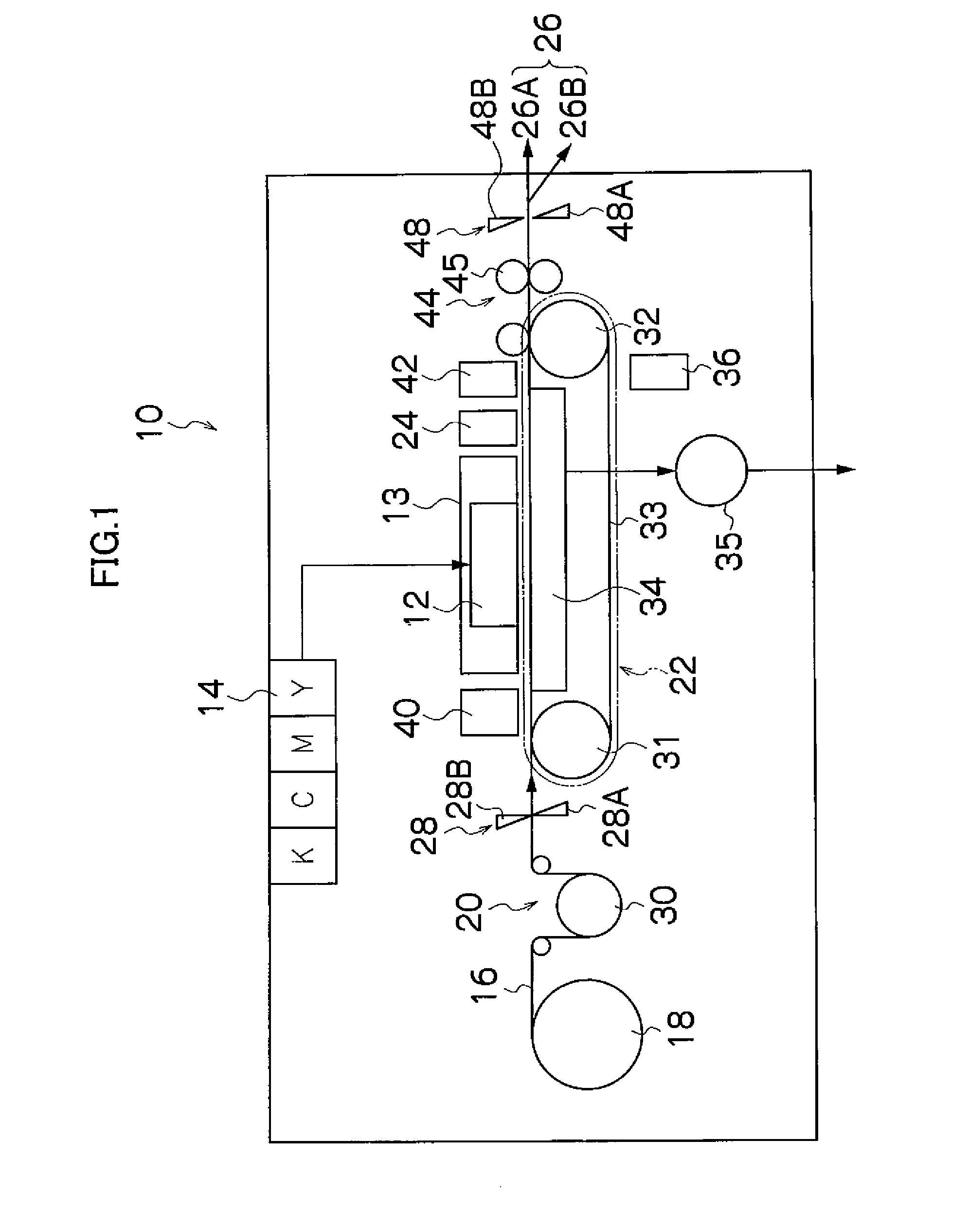
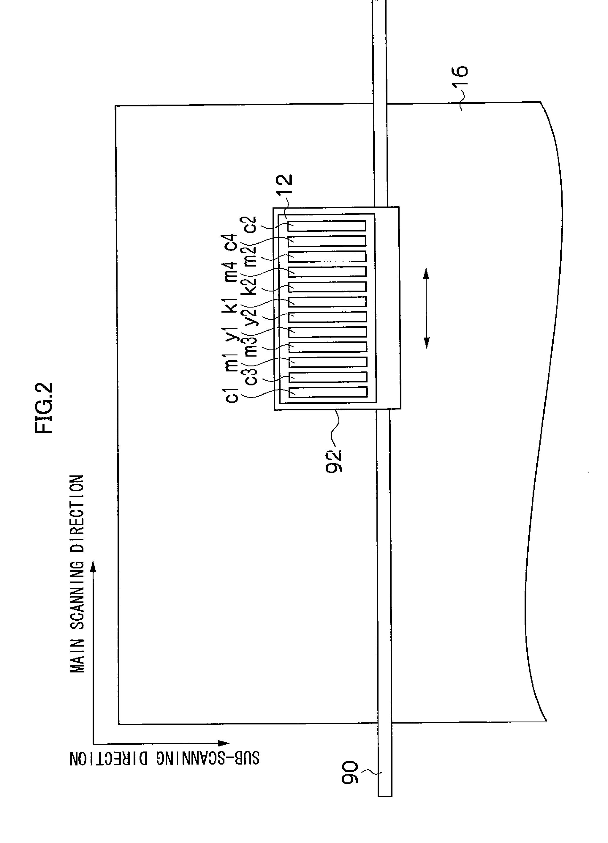
[0036]FIG. 1 is a general schematic drawing showing one embodiment of an inkjet recording apparatus relating to an embodiment of the present invention. As shown in FIG. 1, the inkjet recording apparatus 10 according to the present embodiment comprises: a print head 13 including a recording head 12 which ejects inks (liquids containing coloring material) of respective colors of black (K), cyan (C), magenta (M) and yellow (Y) and a scanning drive mechanism for same (not illustrated); an ink storing and loading unit 14 for storing inks of the respective colors to be supplied to the recording head 12; a paper supply unit 18 for supplying recording paper 16 which forms a recording medium; a decurling unit 20 for removing curl in the recording paper 16; a suction belt conveyance unit 22, disposed facing the nozzle surface (ink ejection surface) of the print unit 13, for conveying the recording paper 16 while keeping the recording paper 16 flat; a print determination unit 24 for reading th...

example 1

Method of Dividing Whole Density Region Into Low Density, Medium Density and High Density

[0139]If the whole region is divided into a low-density region, a medium-density region and a high-density region, then the approximate reference measures for these respective regions are divided as indicated below, using the droplet ejection rate as an indicator (namely, the ratio of dots actually ejected, with respect to the total region of possible droplet ejection). In other words, if the droplet ejection rate is taken to be p, then the reference measure of the low-density region is 0≦p≦¼, the reference measure of the medium-density region is ¼≦p≦⅔, and the reference measure of the high-density region is ⅔

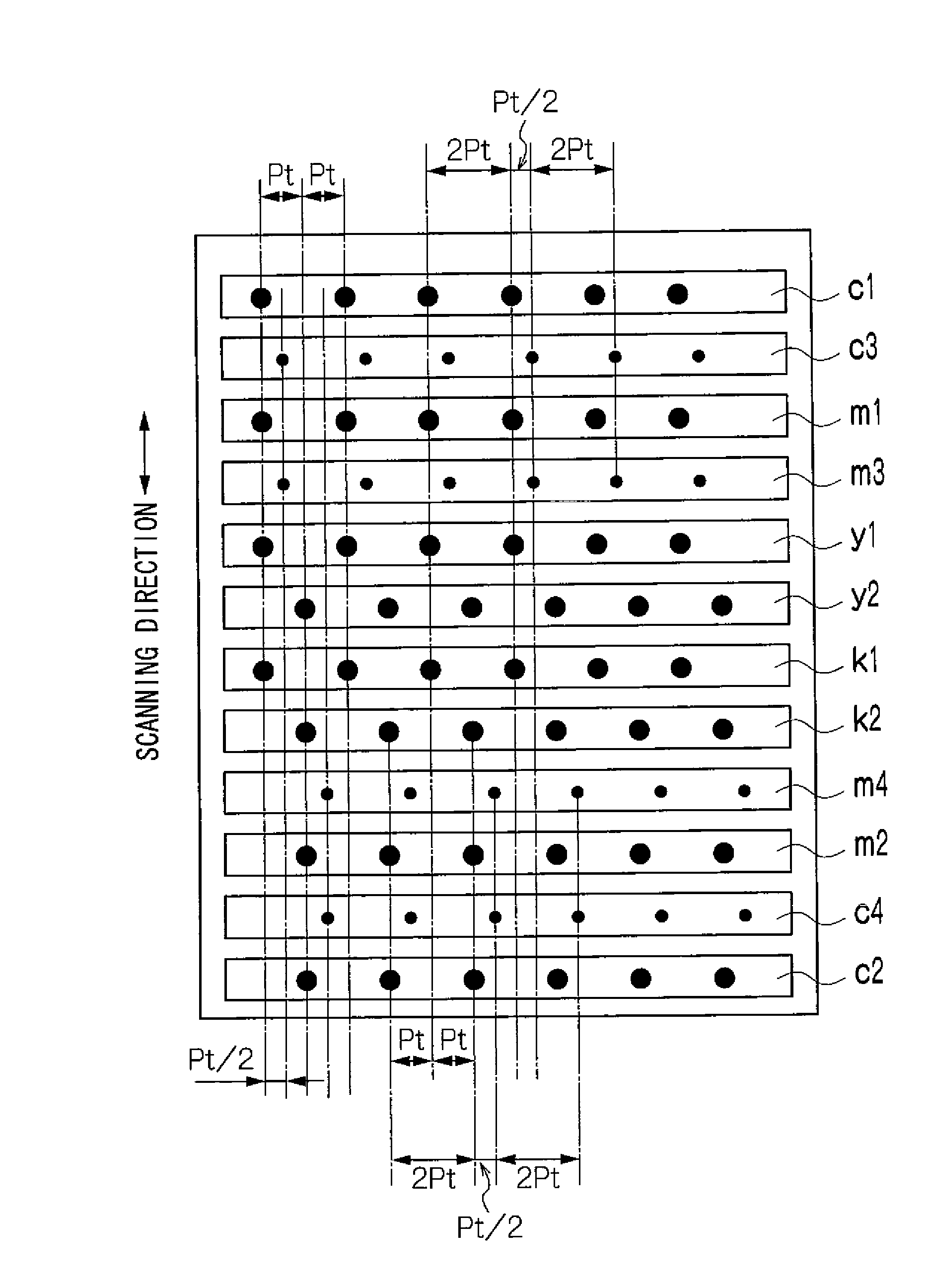
[0140]For reference purposes, FIGS. 14A and 14B shows states where p=¼ and ⅔. FIGS. 14A and 14B show states where the normal dot (main dot) diameter=42 μm, and the dot pitch=21 μm. “p=¼” can be taken to mean “a region where the dots do not overlap with each other”, and “p=⅔” can be tak...

example 2

Method of Dividing Whole Density Region Into Low Density and High Density

[0144]If the whole density region is divided into two regions, a low-density region and a high-density region, then taking the droplet ejection rate (the ratio of the dots actually ejected, with respect to the total region of possible droplet ejection) to be p, the approximate reference measures of the respective regions are such that, for example, a range of 0≦p<¼ is taken as the reference measure for the low-density region and a range of ¼

If Printing a Low-Density Image:

[0145]In this case, similarly to the “Example 1” described above, the dots are ejected sparsely, and therefore banding, which is the issue to which the present application relates...


PUM


Abstract

The image forming method of ejecting liquid droplets containing coloring material toward a recording medium from nozzles including main nozzles and subsidiary nozzles of nozzle rows of a recording head while causing relative movement between the recording medium and the recording head in a relative movement direction that is substantially perpendicular to a direction of alignment of the nozzles of each of the nozzle rows in such a manner that an image is formed by the coloring material on a recording medium, wherein the nozzle rows include first and second nozzle rows which have the main nozzles corresponding to a same coloring material of a particular color and at least one subsidiary nozzle row which includes the subsidiary nozzles corresponding to the same coloring material of the particular color; the first and second nozzle rows and the at least one subsidiary nozzle row are respectively arranged at different positions in terms of the relative movement direction; the at least one subsidiary nozzle row is disposed between the first and second nozzle rows; the subsidiary nozzles are arranged in such a manner that positions of the subsidiary nozzles projected on a straight line in the direction of alignment of the nozzles of each of the nozzle rows are different from positions of the main nozzles projected on the straight line, includes: a measurement step of measuring an amount of inclination of the recording head with respect to the relative movement direction; a correction judgment step of judging whether or not correction is necessary according to the amount of inclination measured in the measurement step; and a correction step of canning out droplet ejection from at least a portion of the subsidiary nozzles, in place of droplet ejection from at least a portion of the main nozzles when Judgment is made, in the correction judgment step, that the correction is necessary, in such a manner that the correction is carried out.

Description

BACKGROUND OF THE INVENTION[0001]1. Field of the Invention[0002]The present invention relates to an image forming method and an image forming apparatus, and more particularly, to an image forming method and an image forming apparatus for recording a desired image by ejecting droplets onto a recording medium while moving a recording head (e.g. inkjet head) provided with a nozzle row which ejects ink droplets and the recording medium relatively with respect to each other.[0003]2. Description of the Related Art[0004]In order to record an image of high quality at high resolution with a serial type inkjet printer which records images onto a recording medium while a recording head is moved reciprocally, a recording head is known which has a composition where the ink ejection nozzles are increased in number only in respect of particular colors (for example, cyan and magenta), and these nozzles are disposed in symmetrical positions with respect to the center of the recording head (see FIG. ...

Claims


Application Information

Patent Timeline
Patent Type & Authority Applications(United States)
IPC IPC(8): B41J29/38
CPCB41J2/2125B41J29/393B41J2/2135
Inventor YAMANOBE, JUN
Owner FUJIFILM CORP
Why Eureka
Try Eureka