[0010]Therefore, an
advantage of the present invention is that a developer and an image forming method are provided wherein
image quality such as reproducibility of fine lines are improved using spherical toners having a sharp particle size distribution and
small particle size while eliminating
reproduction deficiencies in
low input coverage sections which is a
disadvantage of spherical toners and wherein density unevenness can be inhibited even in a document containing entirely
halftone images.
[0011]As a result of extensive studies of the problems mentioned above, the present inventors have found that, in order to eliminate
reproduction deficiency in a
low input coverage section which is a
disadvantage of spherical toners and to inhibit density unevenness in images such as an overall
halftone image, a CMB (Conductive Magnetic
Brush) carrier having a low resistivity should be used as the carrier, and, in order to obtain a superior
solid image while preventing image deficiencies such as a
brush marks and carrier-overs which are disadvantages of the CMB carrier, it is desirable to employ a carrier having the resistivity in a predetermined range. The present inventors have further found that in order to achieve the predetermined range, it is important that the resistivity of the carrier core is lower than a predetermined value and the resistivity of a conductive
powder in a coat resin layer and the resistivity of the coat layer are respectively within a predetermined range.
[0012](1) According to one aspect of the present invention, there is provided an electrophotographic developer formed of a toner and a carrier, the developer comprising a toner having a shape factor of 140 or less and a
volume average particle size distribution GSDv of 1.3 or less; and an electrophotographic carrier having a coat resin layer on a core material, the coat resin layer containing a conductive powder, the core material having a dynamic electric resistivity of 1 Ω·cm or less under an
electric field of 104 V / cm in a form of a magnetic
brush, the conductive powder having an electric resistivity of 101 Ω·cm or greater and 106 Ω·cm or less, and the carrier having an electric resistivity in a range between 10 and 1×10⁸ Ω·cm, wherein the shape factor is defined by an equation,Shape Factor=(ML2 / A)×(Π / 4)×100wherein ML represents the
absolute maximum length of the toner and A represents the
projected area of the toner, and the
volume average particle size distribution GSDv is defined by an equation,GSDv=(D84 / D16)1 / 2 wherein volume D16 represents a particle size where an accumulated volume in an accumulation distribution from smaller size reaches 16% and volume D84 represents a particle size where the accumulated volume in the accumulation distribution reaches 84%.
[0013]In an electrophotographic developer according to this aspect of the present invention, a spherical toner having a
small particle size and a sharp particle size distribution may be used as the toner, and a carrier may be used in which the electric resistivity is adjusted to be in a range of 10 Ω·cm to 108 Ω·cm, the adjustment achieved by using a conductive power having an electrical resistivity of 101 Ω·cm or greater and 106 Ω·cm or less to form an intermediate-resistivity coat resin layer having an electric resistivity of 10 Ω·cm to 1×10⁸ Ω·cm on a low resistivity core material (the core material will also be referred to as “center core” or “core” hereinafter) having a dynamical electric resistivity under an
electric field of 104 V / cm of 1 Ω·cm or less in a form of a magnetic brush. With such a structure, it is possible to improve reproducibility in a low input coverage section, uniformity of a halftone section, and reproducibility of solid images while preventing image deficiencies such as brush marks and carrier-overs.
[0014]The mechanism through which the advantages of reproducibility in a low input coverage section and uniform
reproduction of halftone can be deduced as follows. As described above, because of the spherical shape, the spherical toner has a
surface structure having a relatively uniform
radius of curvature compared to toners obtained by
grinding and having a random shape. As a result of this
surface structure, the distribution of the
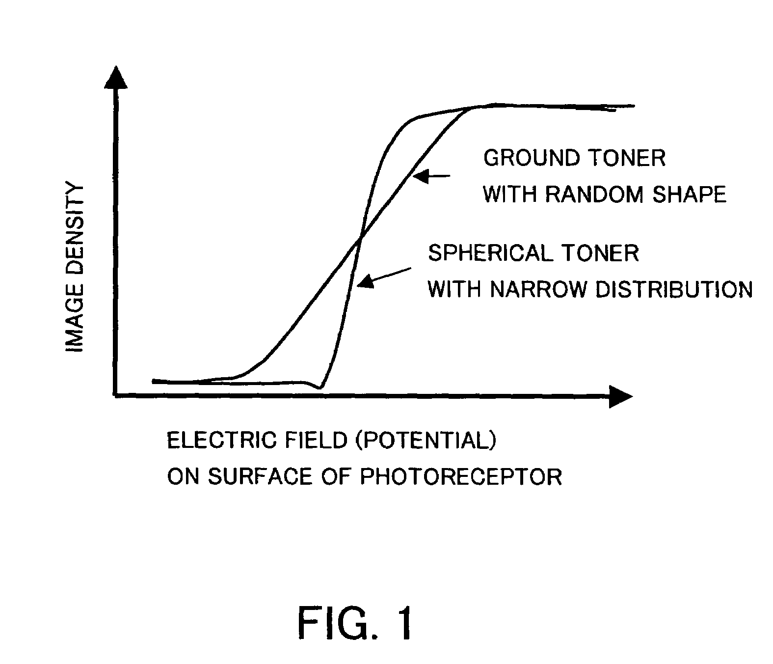
adhesion strength with respect to the carrier is narrow. In addition, because the particle size distribution of the spherical toner is narrow, the distribution of the force acting on the material to which individual toner is to be developed by the developing electric field is narrow. With a combination of these two characteristics, as shown in FIG. 1 which shows the relationship between the developing electric field and the developing amount, the spherical toner has a tendency wherein the developing amount rises more sharply with respect to the developing electric field compared to the randomly shaped toners obtained through
grinding. Although no problem occurs for developing in a region where the development is saturated with respect to the developing electric field, in a low input coverage section within a halftone, the electric field acting on the toner when the toner is developed becomes smaller than the solid section, resulting in a possible case wherein the electric field falls outside the saturation range in the developing electric field-developing weight curve. Because the electric field acting on the toner depends on the input coverage and becomes smaller as the input coverage is reduced, in the spherical toners in which the developing amount more sensitively responds to the developing electric field, the tendency for failing to develop and reproduce in a low input coverage region is higher than in the case of a randomly shaped ground toners having a wider distribution. As a result, it is difficult with the spherical toners to uniformly develop a region of large input coverage and a region of small input coverage, and, in extreme cases, the reproducibility becomes inferior for images having an input coverage value which is less than a certain input coverage value.
[0015]When, however, a CMB carrier is used for the toner as described above, movement of charges are facilitated by
electrostatic induction to the carrier near an image, making it possible to form a developing
electrode in proximity of an electrostatic
latent image of the photoreceptor. With such a structure, the strength of the electric field is increased even in the region of low input coverage compared to IMB (Insulating Magnetic
Brush) carriers and the image can be developed with superior reproducibility. In addition, because the developing
electrode is formed nearer to the photoreceptor, variation in the distance between the developing
electrode and the photoreceptor is small even when the development gap varies due to a deviation of the center of a developing roller, resulting in an
advantage that
local variation in the development electric field within an image of uniform density can be inhibited, so that uniform image can be easily obtained.

