Lens drive device

Active Publication Date: 2020-01-16
TDK TAIWAN
View PDF0 Cites 2 Cited by
  • Summary
  • Abstract
  • Description
  • Claims
  • Application Information

AI Technical Summary

Benefits of technology

The present invention relates to a lens drive device with a conductive portion that connects the coil wiring and the base wiring. The conductive portion is positioned away from the opening periphery of the device, reducing the risk of colliding with other components and preventing the generation of particles. The resin portion covering the conductive portion prevents the particles from entering the optical path and improves connection reliability. Additionally, the use of multiple resin portions or a thinner base board contributes to downsizing and improved heat dissipation of the device. The space between the coil board and base board prevents manufacturing variation and prevents variation in shape of the conductive portion or resin portion. Overall, these technical effects improve the performance and reliability of the lens drive device.

Problems solved by technology

In conventional lens drive devices, however, particles are generated from the connection member and may attach onto an optical path of the lens drive device and flow into an imaging element, and this is a problem.

Method used


Image

  • Lens drive device
  • Lens drive device
  • Lens drive device

Examples


Embodiment Construction

[0038]Hereinafter, the present invention is described based on an embodiment shown in the figures.

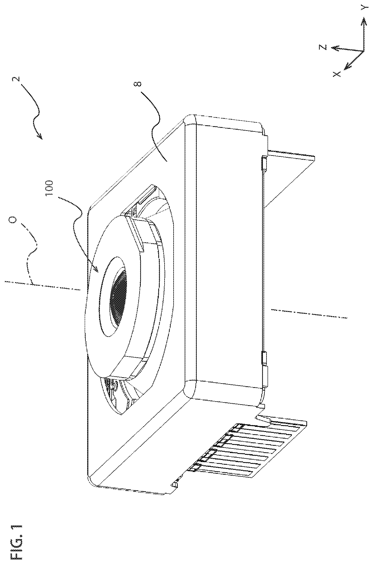
[0039]As shown in FIG. 1, a lens drive device 2 according to an embodiment of the present invention holds a lens 100 at a central part of the lens drive device 2 and drives the lens 100. The lens drive device 2 has a substantially rectangular outer shape when viewed from an optical axis O of the lens 100. The lens drive device 2 includes a case 8 configured to cover the inside of the lens drive device 2 from the positive size hi the Z-axis direction (the incoming side in the optical axis). The case 8 is provided with a through hole where the optical axis O of the lens 100 passes.

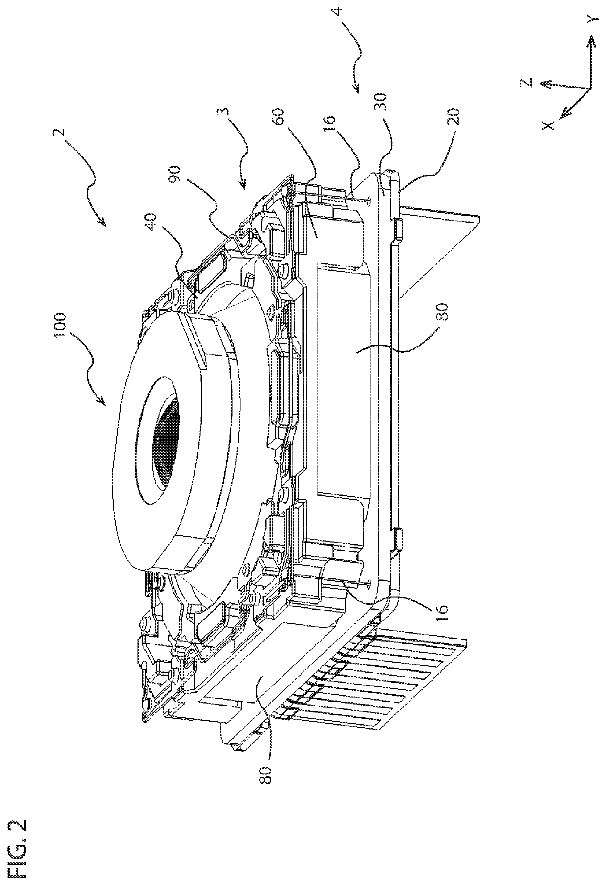
[0040]FIG. 2 is a perspective view of the lens drive device 2 shown in FIG. 1 without the case 8. The lens drive device 2 includes a movable unit 3, a fixed unit 4, and suspension wires 16. In the image stabilization, the movable unit 3 moves in orthogonal. directions to the optical axis along with the lens 100 ...


PUM


Abstract

A lens drive device includes a movable unit, a fixed unit, and a support portion. The movable unit includes a magnet and a lens holder for holding a lens. The fixed unit includes a coil board and a base board. The coil board includes a coil facing the magnet and a coil wiring connected thereto. The base board is disposed opposite to the magnet across the coil board and includes a base wiring and an opening through which the optical axis of the lens passes. The support portion relatively movably connects the movable unit to the fixed unit and supports the movable unit to the fixed unit. A first conductive portion conductively connecting the coil wiring and the base wiring in the fixed unit is disposed away from an opening periphery of the opening to an outside in a radial direction.

Description

BACKGROUND OF THE INVENTION[0001]The present invention relates to an image-stabilizer lens drive device favorably used for camera module of mobile phones, for example.[0002]In lens drive devices favorably used for camera module of mobile phones, developed are image-stabilizer lens drive devices that carry out optical image stabilization (OIS) by moving a lens holder holding a lens in orthogonal directions to an optical axis (e.g., Patent Document 1). In such lens drive devices, electric power is supplied to a drive coil for driving the lens via FPC, wirings of rigid board, springs, or the like.[0003]A conductive connection member, such as solder, is used for a connection part between each wiring of the board, between wirings of the board and the springs, or the like. The connection member, such as solder, is melted and solidified by heating and connects the wirings. In conventional lens drive devices, however, particles are generated from the connection member and may attach onto an...

Claims


Application Information

Patent Timeline
IPC IPC(8): G02B7/09H04N5/232H04N5/225G03B5/02
CPCG02B7/09H04N5/232H04N5/2254G03B2205/0069H04N5/2252H04N5/2257G03B5/02G03B5/00H04N23/57H04N23/55G03B2205/0015G03B3/10G02B27/646G02B7/08H04N23/687H04N23/51H04N23/60
Inventor SUZUKIICHIHASHI, SHUSUKE
Owner TDK TAIWAN
Why Eureka
Try Eureka