Method and System for Illumination Adjustment

a technology of illumination adjustment and illumination, applied in the field of illumination and imaging systems and methods, can solve the problems of poor quality or inaccurate image and optical measurement of objects, especially when obtained via electronic imaging equipment (also referred to as “machine vision”), saturation and loss of information in other parts of the image, and achieve low cost manufacturing. , good color representation, high fill factor

Inactive Publication Date: 2008-06-26
COGENETENS
View PDF7 Cites 19 Cited by
  • Summary
  • Abstract
  • Description
  • Claims
  • Application Information

AI Technical Summary

Benefits of technology

[0014]The LCD elements are individually controllable via said control instructions such as to provide a range of levels of optical transparencies between a minimum value, in which the corresponding LCD element allows substantially no illumination light therethrough, and a maximum value, in which the maximum illumination intensity is allowed to be projected therethrough towards the object.
[0015]Features of LCD-based illumination units include the following: LCD technology is very well developed and widely available, and provide good color representation; and such units are analogue devices, enabling the degree of illumination control to be controlled directly.
[0019]In other embodiments, the programmable illumination unit may be based on a Liquid Crystal on Silicon (LCOS) device. Features of LCOS-based illumination units include the following: LCOS technology is a new technology with potential for low cost manufacture; analogue devices with good color representation; high fill factor with no “screen door” effect; small pixels and high resolution may be provided.
[0020]In other embodiments, the programmable illumination unit may be based on a Grating Light Valve (GLV) device. Features of GLV-based illumination units include the following: GLV technology is suitable for monochromatic light sources; may be manufactured in a standard IC process, providing low cost, high resolution linear arrays.
[0058]Standard SLM devices typically have dynamic range of 8 bits so that utilizing a standard video imaging device with 8 bits dynamic range effectively results in a system having a dynamic range of 16 bits, which is double the imaging device dynamic range. Advanced processing capabilities that are currently available coupled with fast refresh rate of the SLM devices are such that the time required for acquiring and analyzing the images is very short, and video rates of 30 frames per second can be achieved.

Problems solved by technology

Imaging and optical measurement of objects, particularly when obtained via electronic imaging equipment (also referred to as “machine vision”), can sometimes be of poor quality or inaccurate when there is an imbalance in the intensity of light reflected therefrom from an illumination optics, whether natural or artificial.
While the illumination optics may provide a uniform illumination to the object in question, there may sometimes be large reflectance variations of the measured object surface due to variations in surface characteristics, for example, and such reflectance variations may be difficult to deal with.
When imaging a surface of such objects illuminated with uniform illumination, the resultant image may sometimes be dark in some areas of the image while highlighted areas cause saturation and loss of information in other parts of the image.

Method used


Image

  • Method and System for Illumination Adjustment
  • Method and System for Illumination Adjustment
  • Method and System for Illumination Adjustment

Examples


Embodiment Construction

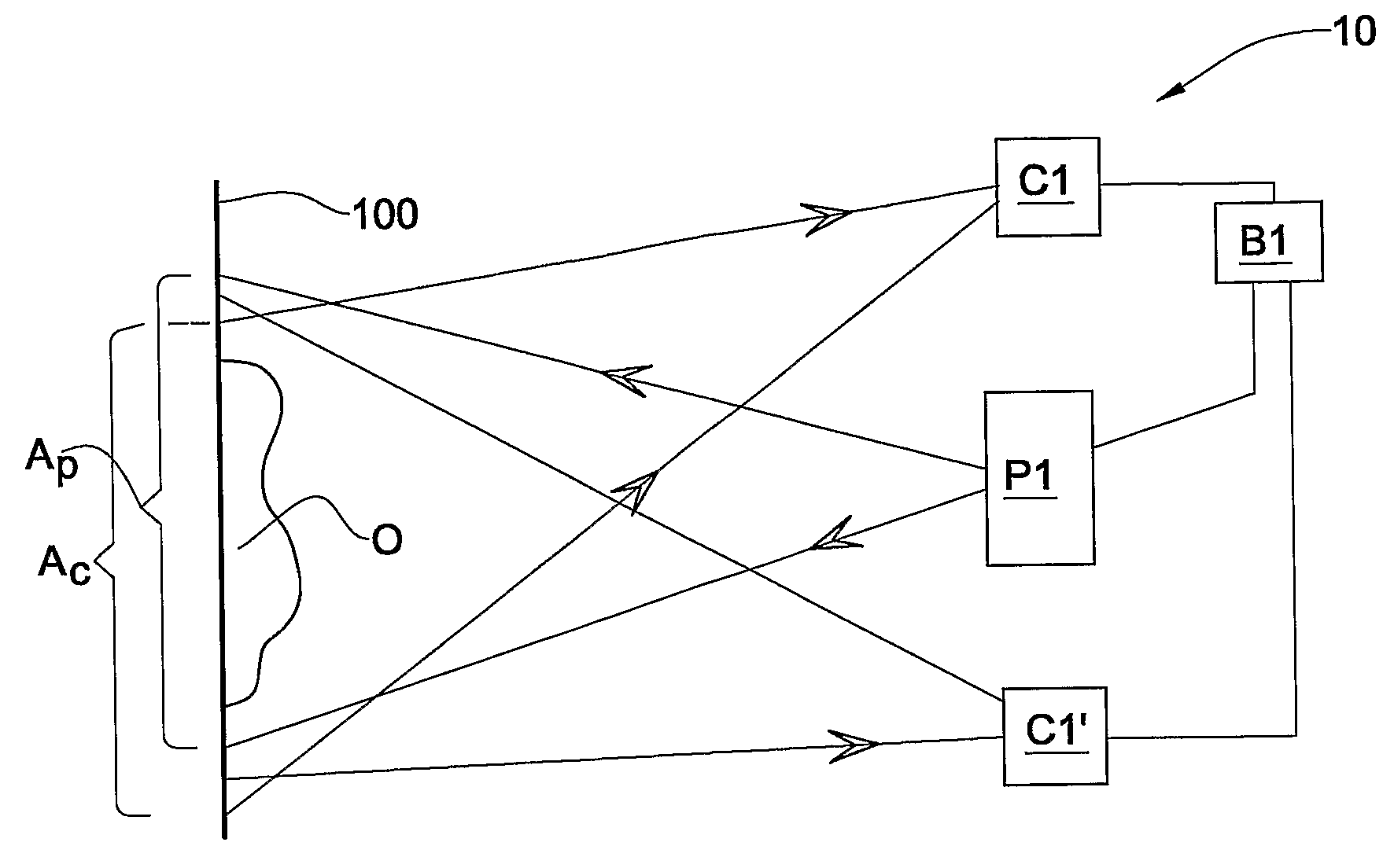
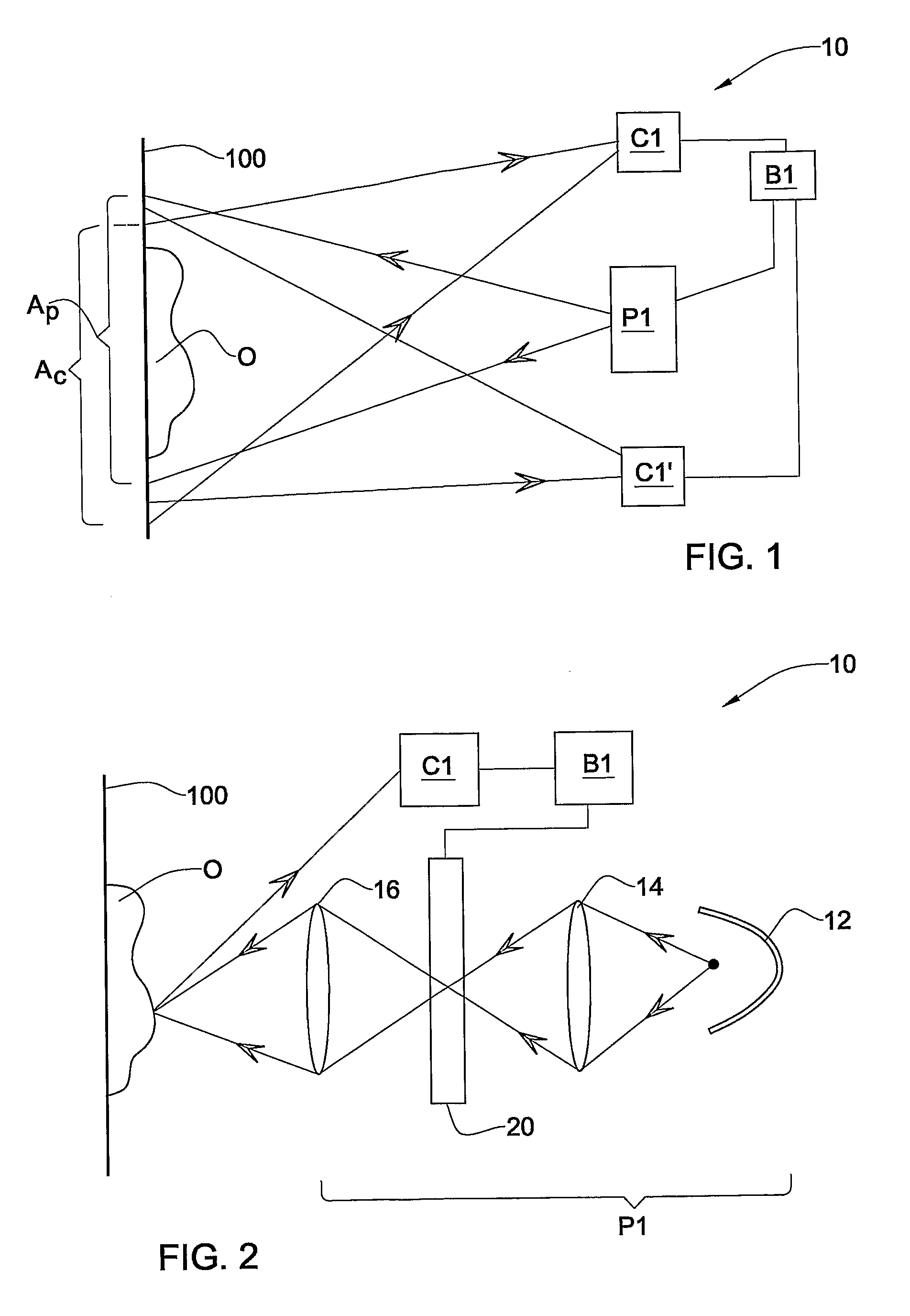
[0071]In a first embodiment of the invention, a system for illumination and imaging, illustrated in FIGS. 1 and 2, and generally designated with the reference numeral 10, comprises a controllable illumination unit P1, at least one imaging device C1 (in FIG. 1, an additional imaging device C1′ is also shown), and an illumination control unit B1 operatively connected or coupled to the imaging device(s) and to the illumination unit P1. According to this embodiment, the system is set up such that illumination radiation from illumination unit P1 projected to an object is reflected (generally non-specularly) thereby towards one or more imaging devices C1, C1′, wherein an image taken of the object by the imaging device comprises reflectance data associated with the object.

[0072]Referring in particular to FIG. 2, the controllable illumination unit P1 comprises an illumination source 12, a focusing optics 14, and a spatial light modulator (SLM) such as for example a controllable Liquid Cryst...


PUM


Abstract

A method and system are provided for illuminating and imaging an object, wherein the illumination of the object is controlled by means of feedback based on the light intensity obtained from the object using one method of illumination, such as to provide a modified illumination that will result in a more uniform reflectance from the object.

Description

FIELD OF THE INVENTION[0001]This invention relates to illumination and imaging systems and methods. In particular, the invention relates to such systems and methods that may be applied to 3D surface reconstruction and other optical measurements.BACKGROUND OF THE INVENTION[0002]Imaging and optical measurement of objects, particularly when obtained via electronic imaging equipment (also referred to as “machine vision”), can sometimes be of poor quality or inaccurate when there is an imbalance in the intensity of light reflected therefrom from an illumination optics, whether natural or artificial. While the illumination optics may provide a uniform illumination to the object in question, there may sometimes be large reflectance variations of the measured object surface due to variations in surface characteristics, for example, and such reflectance variations may be difficult to deal with. Large-scale industrial objects such as metal parts used in the automotive industry, printed circui...

Claims


Application Information

Patent Timeline
Patent Type & Authority Applications(United States)
IPC IPC(8): G03B21/26
CPCG03B21/26
Inventor SEGEV, AVNER
Owner COGENETENS
Why Eureka
Try Eureka